AUTOMATIC TRANSMISSION UNIT REASSEMBLY

-
BEARING POSITION
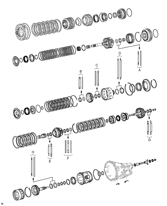
Bearing Position Position Front Race Diameter
Inside/Outside
Thrust Bearing Diameter
Inside/Outside
Rear Race Diameter
Inside/Outside
A - 36.2 mm (1.425 in.) / 58.2 mm (2.291 in.) 44.0 mm (1.732 in.) / 62.0 mm (2.441 in.) B - 34.5 mm (1.358 in.) / 49.4 mm (1.945 in.) 36.6 mm (1.441 in.) / 51.9 mm (2.043 in.) C 46.5 mm (1.831 in.) / 60.1 mm (2.366 in.) 47.0 mm (1.850 in.) / 61.9 mm (2.437 in.) - D - 71.9 mm (2.831 in.) / 85.6 mm (3.370 in.) 72.7 mm (2.858 in.) / 89.2 mm (3.512 in.) E 30.0 mm (1.181 in.) / 49.9 mm (1.965 in.) 31.0 mm (1.221 in.) / 53.1 mm (2.091 in.) - F 31.5 mm (1.240 in.) / 53.0 mm (2.0866 in.) 28.7 mm (1.130 in.) / 52.3 mm (2.059 in.) 28.7 mm (1.130 in.) / 50.4 mm (1.984 in.) G - 30.5 mm (1.201 in.) / 55.7 mm (2.189 in.) 33.5 mm (1.319 in.) / 59.0 mm (2.323 in.) H - 58.9 mm (2.319 in.) / 77.3 mm (3.043 in.) 62.0 mm (2.441 in.) / 82.5 mm (3.248 in.) -
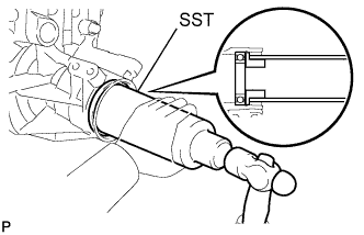
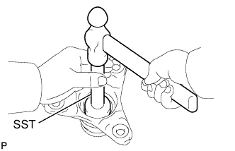
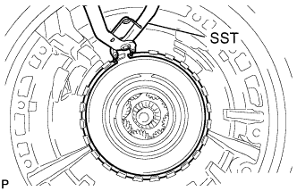
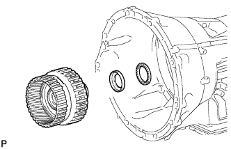
INSTALL OUTPUT SHAFT REAR RADIAL BALL BEARING
-
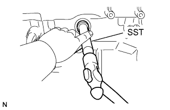
Using SST, tap in the bearing to the transmission case.
- SST
- 09316-60011 ( 09316-00011, 09316-00021 )
-
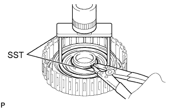
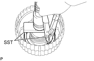
Using needle-nose pliers, install the snap ring.
-
-
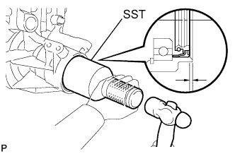
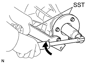
INSTALL AUTOMATIC TRANSMISSION REAR OIL SEAL
-
Coat the lip of a new oil seal with MP grease.
-
Using SST and a hammer, tap in the oil seal until it fits with the transmission case.
- SST
- 09214-76011
Standard oil seal depth 3.5 +/-0.2 mm (0.138 +/-0.008 in.)
-
-
INSTALL NO. 2 BRAKE PISTON
-
Coat 3 new O-rings with ATF, and install them to the brake piston.
-
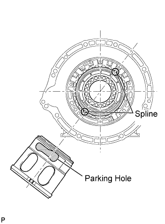
Install the brake piston to the transmission case.
Tech Tips
Make sure that the parking hole of the brake piston is on the bottom side by engaging the brake piston's 2 protrusions to the transmission case's spline grooves. (One groove is 3 places clockwise from the top, and the other is 2 places clockwise from the bottom).
-
Install the brake return spring to the transmission case.
-
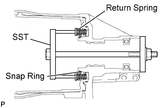
Set SST on the brake piston return spring, tighten SST and compress the return spring.
- SST
- 09380-50010
-
Using SST, install the snap ring.
- SST
- 09350-30020 ( 09350-07070 )
-
-
SELECT NO. 2 BRAKE FLANGE
-
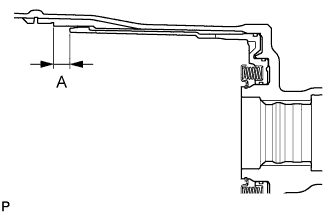
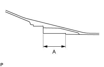
Measure length A (from the tip of the No. 2 brake piston to the step in the transmission case) in the illustration. *1
Standard 14.77 to 15.37 mm (0.5815 to 0.6051 in.) -
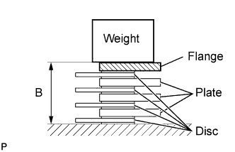
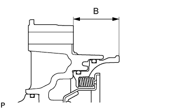
Assemble the 4 No. 2 brakes discs, 3 No. 2 brake plates, and No. 2 brake flange as shown in the illustration. Then with a weight fixture of 500 g (17.64 oz) or less placed on the flange, measure length B. *2
Standard 14.11 to 14.69 mm (0.5555 to 0.5783 in.) -
Choose a No. 2 brake flange so that the value of measured length A minus length B (from steps *1 and *2) is 0.52 to 0.82 mm (0.0204 to 0.0323 in.).
Flange thickness Mark Thickness 0 1.95 to 2.05 mm (0.0768 to 0.0807 in.) 1 2.05 to 2.15 mm (0.0807 to 0.0846 in.) 2 2.15 to 2.25 mm (0.0846 to 0.0886 in.) 3 2.25 to 2.35 mm (0.0886 to 0.0925 in.) 4 2.35 to 2.45 mm (0.0925 to 0.0965 in.) 5 2.45 to 2.55 mm (0.0965 to 0.1004 in.) 6 2.55 to 2.65 mm (0.1004 to 0.1043 in.) 7 2.65 to 2.75 mm (0.1043 to 0.1083 in.) 8 2.75 to 2.85 mm (0.1083 to 0.1122 in.)
-
-
INSTALL DIRECT CLUTCH PISTON
-
Coat a new O-ring with ATF, and install it to the rear clutch drum sub-assembly.
-
Coat a new O-ring with ATF, and install it to the clutch piston.
-
Install the clutch piston to the rear clutch drum sub-assembly.
-
Coat a new O-ring with ATF, and install it to the No. 2 clutch balancer.
-
Install the direct clutch piston return spring sub-assembly and balancer to the rear clutch drum sub-assembly.
-
Place SST on the clutch balancer and compress the return spring with a press.
- SST
- 09387-00020
-
Using SST, install the snap ring.
- SST
- 09350-30020 ( 09350-07070 )
-
-
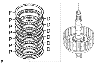
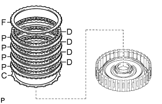
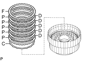
INSTALL NO. 2 CLUTCH DISC SET
-
Install the 6 plates, 6 discs and flange to the rear clutch drum.
Install in order P - D - P - D - P - D - P - D - P - D - P - D - F Tech Tips
P = Plate
D = Disc
F = Flange
Note
Before assembling new discs, soak them in ATF for at least 2 hours.
-
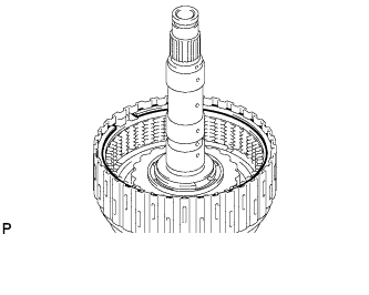
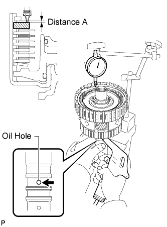
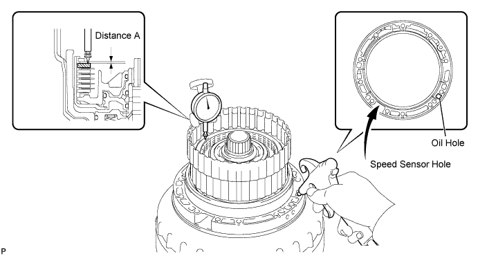
Temporarily install the snap ring.
-
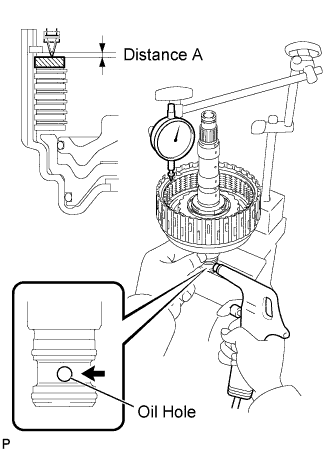
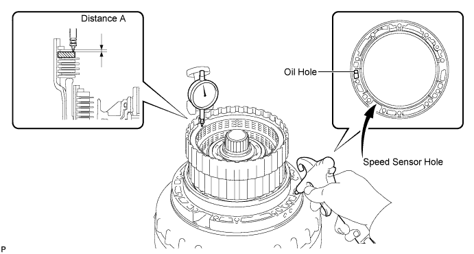
Using a dial indicator, measure the moving distance (distance A) of the clutch flange at both ends across the diameter while blowing compressed air (196 kPa, 2.0 kgf*cm2, 28 psi) from the oil hole as shown in the illustration. Then choose from the 9 flange thicknesses in the table so that the measured value is within the standard value.
Standard 0.90 to 1.20 mm (0.0354 to 0.0472 in.) Flange thickness Mark Thickness 40 3.95 to 4.05 mm (0.1555 to 0.1594 in.) 41 4.05 to 4.15 mm (0.1594 to 0.1634 in.) 42 4.15 to 4.25 mm (0.1634 to 0.1673 in.) 43 4.25 to 4.35 mm (0.1673 to 0.1713 in.) 44 4.35 to 4.45 mm (0.1713 to 0.1752 in.) 45 4.45 to 4.55 mm (0.1752 to 0.1791 in.) 46 4.55 to 4.65 mm (0.1791 to 0.1831 in.) 47 4.65 to 4.75 mm (0.1831 to 0.1870 in.) 48 4.75 to 4.85 mm (0.1870 to 0.1909 in.) -
Temporarily remove the snap ring, attach the selected flange and restore the snap ring.
-
-
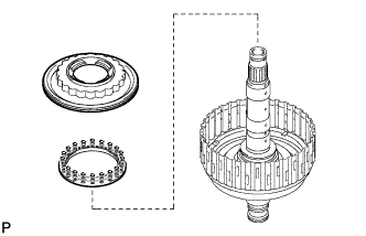
CONNECT DIRECT CLUTCH ASSEMBLY
-
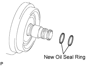
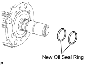
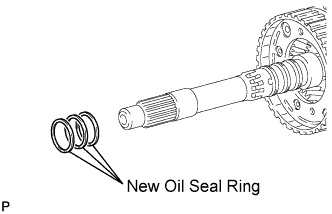
Coat 2 new oil seal rings with ATF, and install them to the direct clutch drum sub-assembly.
Note
Do not expand the ring ends excessively.
-
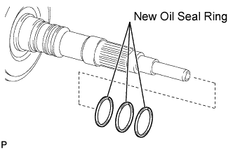
Coat 3 new oil seal rings with ATF, and install them to the output shaft.
Note
Do not expand the ring ends excessively.
-
Install the thrust needle roller bearing and thrust bearing race.
Standard bearing and race diameter Item Inside Outside Bearing 30.5 mm (1.201 in.) 55.7 mm (2.189 in.) Race 33.5 mm (1.319 in.) 59.0 mm (2.323 in.) Note
Use a small amount of MP grease to make the thrust bearing and thrust bearing race stay securely in place.
-
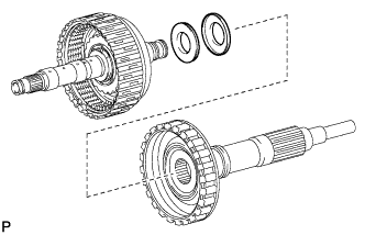
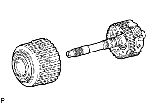
Connect the direct clutch assembly to the output shaft.
-
-
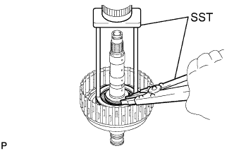
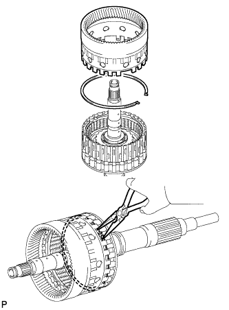
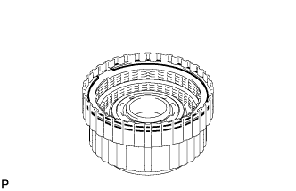
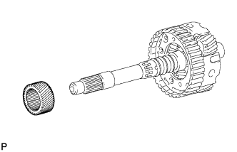
INSTALL REAR PLANETARY RING GEAR
-
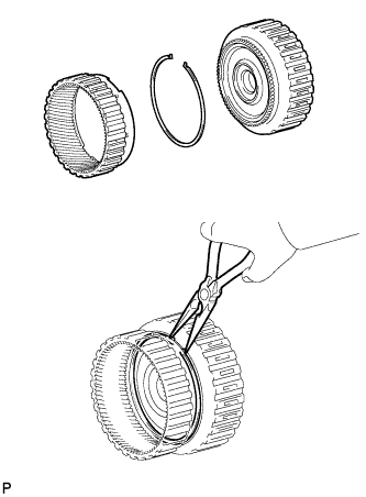
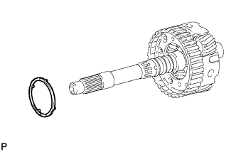
Install the snap ring to the groove of the output shaft.
-
Using needle-nose pliers, attach the snap ring to install the ring gear to the output shaft.
-
-
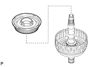
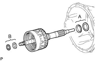
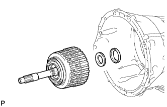
INSTALL DIRECT CLUTCH ASSEMBLY WITH REAR PLANETARY RING GEAR AND OUTPUT SHAFT SUB-ASSEMBLY
-
Install the 2 thrust needle bearings, 2 thrust bearing races, direct clutch with rear planetary ring gear and output shaft to the transmission case.
Standard bearing and race diameter Item Inside Outside Race A 62.0 mm (2.441 in.) 82.5 mm (3.248 in.) Bearing A 58.9 mm (2.319 in.) 77.3 mm (3.043 in.) Race B 28.7 mm (1.130 in.) 50.4 mm (1.984 in.) Bearing B 28.7 mm (1.130 in.) 52.3 mm (2.059 in.) Note
Use a small amount of MP grease to make the thrust bearing and thrust bearing race stay securely in place.
-
-
INSTALL AUTOMATIC TRANSMISSION FLANGE YOKE ASSEMBLY
-
Using SST, install a new oil seal to the automatic transmission flange yoke.
- SST
- 09950-60010 ( 09951-00410 )
- 09950-70010 ( 09951-07100 )
-
Install the rear cover sleeve and 2 output shaft rear bearing No. 1 spacers.
-
Install the automatic transmission flange yoke.
-
Set SST.
- SST
- 09330-00021
- 09950-30012 ( 09955-03040 )
-
Using SST and a 30 mm socket wrench, temporarily install and tighten a new nut.
- Torque:
- 126 N*m { 1,285 kgf*cm, 93 ft.*lbf }
-
-
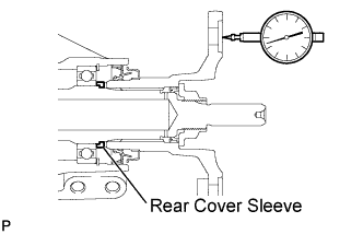
SELECT REAR COVER SLEEVE
-
Using a dial indicator, measure the output shaft end play. Then choose from the 15 sleeve thicknesses in the table so that the measured value is within the standard value.
Standard end play 0.21 to 0.36 mm (0.0083 to 0.0142 in.) Sleeve thickness Mark Thickness 02 1.725 to 1.775 (0.0679 to 0.0699 in.) 03 1.775 to 1.825 (0.0699 to 0.0719 in.) 04 1.825 to 1.875 (0.0719 to 0.0738 in.) 05 1.875 to 1.925 (0.0738 to 0.0758 in.) 06 1.925 to 1.975 (0.0758 to 0.0778 in.) 07 1.975 to 2.025 (0.0778 to 0.0797 in.) 08 2.025 to 2.025 (0.0778 to 0.0797 in.) 09 2.075 to 2.125 (0.0817 to 0.0837 in.) 10 2.125 to 2.175 (0.0837 to 0.0856 in.) 11 2.175 to 2.225 (0.0778 to 0.0797 in.) 12 2.225 to 2.275 (0.0876 to 0.0896 in.) 13 2.275 to 2.325 (0.0896 to 0.0915 in.) 14 2.325 to 2.375 (0.0915 to 0.0935 in.) 15 2.375 to 2.425 (0.0935 to 0.0955 in.) 16 2.425 to 2.475 (0.0955 to 0.0974 in.) -
Temporarily remove the lock nut, flange yoke, 2 spacers and sleeve, attach the selected sleeve and restore the flange yoke.
-
Using a chisel and hammer, securely stake the nut.
-
-
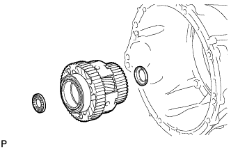
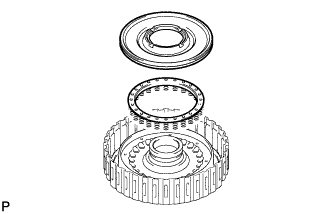
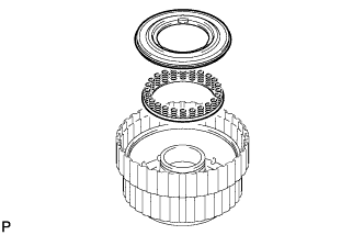
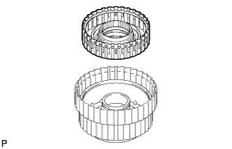
INSTALL REAR PLANETARY GEAR ASSEMBLY
-
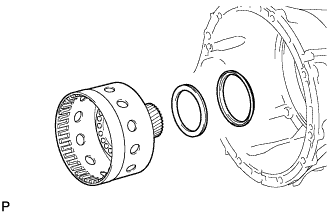
Install the thrust bearing race, rear planetary gear assembly and thrust needle roller bearing to the transmission case.
Standard bearing and race diameter Item Inside Outside Race 31.5 mm (1.240 in.) 53.0 mm (2.0866 in.) Bearing 31.0 mm (1.221 in.) 53.1 mm (2.091 in.) Note
-
Before installing the rear planetary gear, apply ATF to rear planetary gear bush's sliding surfaces. After the installation, check that the rear planetary gear rotates smoothly.
-
Use a small amount of MP grease to make the thrust bearing and thrust bearing race stay securely in place.
-
-
-
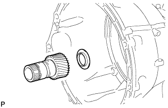
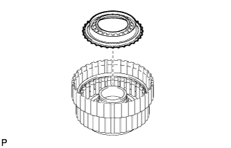
INSTALL REAR PLANETARY SUN GEAR ASSEMBLY
-
Install the thrust bearing race and sun gear to the transmission case.
Standard bearing race diameter Item Inside Outside Race 30.0 mm (1.181 in.) 49.9 mm (1.965 in.) Note
-
Before installing the sun gear, apply ATF to sun gear bush's sliding surfaces. After the installation, check that the sun gear rotates smoothly.
-
Use a small amount of MP grease to make the thrust bearing race stay securely in place.
-
-
-
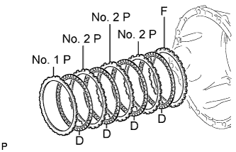
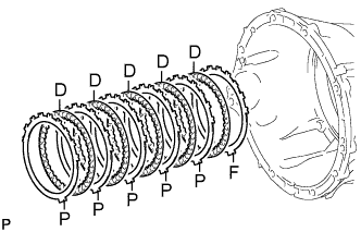
INSTALL NO. 2 BRAKE DISC SET
-
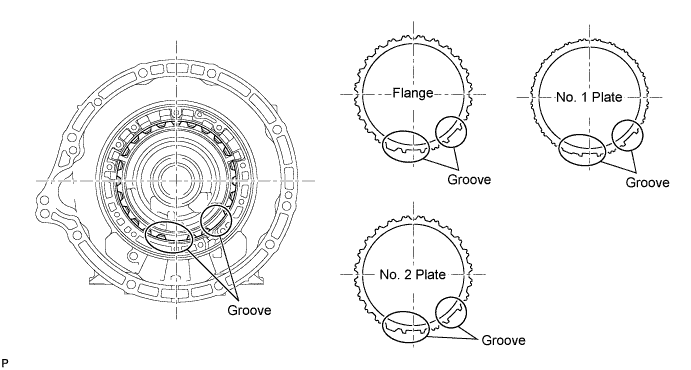
Install the selected flange, 4 discs, 3 No. 2 plates and No. 1 plate.
Install in order F - D - No. 2 P - D - No. 2 P - D - No. 2 P - D - No. 1 P Tech Tips
F = Flange
D = Disc
P = Plate
Tech Tips
Assemble the transmission case, flanges and plates by aligning their grooves as shown in the illustration.
Note
Before assembling new discs, soak them in ATF for at least 2 hours.
-
-
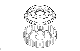
INSTALL NO. 1 1-WAY CLUTCH
-
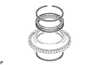
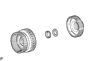
Install the 1-way clutch to the outer race with the 2 snap rings.
Note
Do not mistake the direction of the 1-way clutch.
-
-
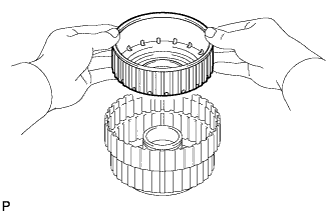
INSPECT NO. 1 1-WAY CLUTCH
-
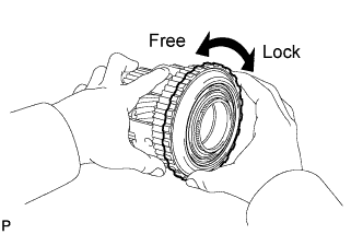
Set the 1-way clutch to the rear planetary gear.
-
Hold the rear planetary gear assembly and turn the 1-way clutch.
-
Check that the 1-way clutch turns freely counterclockwise and locks clockwise.
If there is a problem with the 1-way clutch, replace it.
-
-
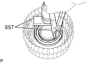
INSTALL 1-WAY CLUTCH OUTER RACE WITH NO. 1 1-WAY CLUTCH
-
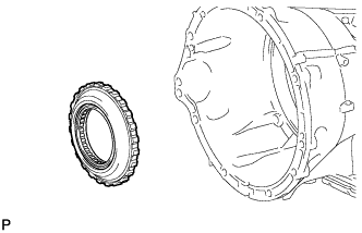
Install the 1-way clutch outer race with 1-way clutch to the transmission case.
-
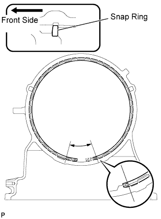
Using SST, install the snap ring to the transmission case.
- SST
- 09350-30020 ( 09350-07060 )
Note
-
-
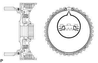
Install the snap ring so that its tapered face is facing the front side of the transmission case.
-
Install the snap ring so that its gap end is within the range shown in the illustration.
-
-
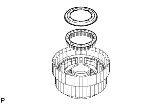
INSTALL SUN GEAR INPUT DRUM SUB-ASSEMBLY
-
Install the thrust bearing race, thrust needle roller bearing and sun gear input drum.
Standard bearing and race diameter Item Inside Outside Race 72.7 mm (2.858 in.) 89.2 mm (3.512 in.) Bearing 71.9 mm (2.831 in.) 85.6 mm (3.370 in.) Note
-
Before installing the sun gear input drum, apply ATF to sun gear input drum bush's sliding surfaces. After the installation, check that the sun gear input drum rotates smoothly.
-
Use a small amount of MP grease to make the thrust bearing and thrust bearing race stay securely in place.
-
-
-
INSTALL FORWARD CLUTCH PISTON
-
Coat 2 new O-rings with ATF, and install it to the clutch piston.
-
Install the clutch piston to the forward clutch drum.
-
Coat a new O-ring with ATF, and install it to the No. 1 clutch balancer.
-
Install the forward clutch return spring sub-assembly and clutch balancer to the forward clutch drum.
-
Place SST on the clutch balancer, and compress the clutch balancer with a press.
- SST
- 09380-50010
-
Using SST, install the snap ring.
- SST
- 09350-30020 ( 09350-07070 )
Note
-
Be sure that the end gap of the snap ring is not aligned with the spring retainer claw.
-
Stop pressing when the balancer is lowered to the place 1 to 2 mm (0.039 to 0.078 in.) from the snap ring groove to prevent spring sheet deformation.
-
Do not expand the snap ring excessively.
-
-
INSTALL FORWARD MULTIPLE CLUTCH DISC SET
-
Install the cushion plate, 4 plates, 4 discs and flange to the forward clutch drum.
Install in order C - P - D - P - D - P - D - P - D - F Tech Tips
C = Cushion
P = Plate
D = Disc
F = Flange
Note
-
Assemble the cushion plate by facing its marked side towards the plates.
-
Before assembling new discs, soak them in ATF for at least 2 hours.
-
-
Temporarily install the snap ring.
-
Temporarily assemble the front planetary gear assembly to the forward clutch assembly.
-
Using a dial indicator, measure the moving distance (distance A) of the clutch flange at both ends across the diameter while blowing compressed air (196 kPa, 2.0 kgf*cm, 28 psi) from the oil hole as shown in the illustration. Then choose from the 9 flange thicknesses in the table so that the measured value is within the standard value.
Standard 0.90 to 1.20 mm (0.0354 to 0.0472 in.) Flange thickness Mark Thickness 0 4.35 to 4.45 mm (0.1713 to 0.1752 in.) 1 4.45 to 4.55 mm (0.1752 to 0.1791 in.) 2 4.55 to 4.65 mm (0.1791 to 0.1831 in.) 3 4.65 to 4.75 mm (0.1831 to 0.1870 in.) 4 4.75 to 4.85 mm (0.1870 to 0.1909 in.) 5 4.85 to 4.95 mm (0.1909 to 0.1949 in.) 6 4.95 to 5.05 mm (0.1949 to 0.1988 in.) 7 5.05 to 5.15 mm (0.1988 to 0.2029 in.) 8 5.15 to 5.25 mm (0.2029 to 0.2067 in.) -
Temporarily remove the snap ring, attach the selected flange and restore the snap ring.
-
Remove the front planetary gear assembly.
-
-
INSTALL FRONT PLANETARY RING GEAR
-
Install the snap ring to the groove of forward clutch drum.
-
Using needle-nose pliers, attach the snap ring to install the ring gear to the forward multiple disc clutch assembly.
Note
Check that the snap ring is securely fit into the groove by looking through the ring gear slots on both sides.
-
-
INSTALL MULTIPLE DISC CLUTCH HUB
-
Install the thrust needle bearing, thrust bearing race and multiple disc clutch hub to the forward clutch assembly.
Standard bearing and race diameter Item Inside Outside Bearing 34.5 mm (1.358 in.) 49.4 mm (1.945 in.) Race 36.6 mm (1.441 in.) 51.9 mm (2.043 in.) Note
Use a small amount of MP grease to make the thrust bearing and thrust bearing race stay securely in place.
-
-
INSTALL FORWARD CLUTCH ASSEMBLY WITH FRONT PLANETARY RING GEAR AND MULTIPLE DISC CLUTCH HUB
-
Install the thrust bearing race, thrust needle bearing and forward clutch assembly with front planetary ring gear and multiple disc clutch hub to the transmission case.
Standard bearing and race diameter Item Inside Outside Bearing 47.0 mm (1.850 in.) 61.9 mm (2.437 in.) Race 46.5 mm (1.831 in.) 60.1 mm (2.366 in.) Note
-
Before installing the forward clutch drum, apply ATF to forward clutch drum bush's sliding surfaces. After the installation, check that the forward clutch drum rotates smoothly.
-
Use a small amount of MP grease to make the thrust bearing and thrust bearing race stay securely in place.
-
-
-
INSTALL NO. 3 CLUTCH PISTON
-
Coat a new O-ring with ATF, and install it to the overdrive direct clutch drum sub-assembly.
-
Coat a new O-ring with ATF, and install it to the piston.
-
Install the piston to the direct clutch drum.
-
Coat a new O-ring with ATF, and install it to the No. 3 clutch balancer.
-
Install the overdrive clutch return spring and balancer to the direct clutch drum.
-
Place SST on the clutch balancer, and compress the clutch balancer with a press.
- SST
- 09380-50010
-
Using SST, install the snap ring.
- SST
- 09350-30020 ( 09350-07070 )
Note
-
Be sure that the end gap of the snap ring is not aligned with the spring retainer claw.
-
Stop pressing when the balancer is lowered to the place 1 to 2 mm (0.039 to 0.078 in.) from the snap ring groove to prevent spring sheet deformation.
-
Do not expand the snap ring excessively.
-
-
INSTALL REVERSE CLUTCH DRUM SUB-ASSEMBLY
-
Coat 3 new O-rings with ATF, and install them to the drum.
-
Install the drum to the overdrive direct clutch drum sub-assembly.
-
-
INSTALL REVERSE CLUTCH PISTON
-
Coat a new O-ring with ATF, and install it to the piston.
-
Install the piston, reverse clutch piston return spring and reverse clutch balancer.
-
Place SST on the clutch balancer, and compress the clutch balancer with a press.
- SST
- 09380-50010
-
Using SST, install the snap ring.
- SST
- 09350-30020 ( 09350-07070 )
Note
-
Be sure that the end gap of the snap ring is not aligned with the spring retainer claw.
-
Stop pressing when the balancer is lowered to the place 1 to 2 mm (0.039 to 0.078 in.) from the snap ring groove to prevent spring sheet deformation.
-
Do not expand the snap ring excessively.
-
-
INSTALL REVERSE CLUTCH DISC SET
-
Install the cushion plate, 5 plates, 5 discs and flange to the No. 2 reverse clutch drum.
Install in order C - P - D - P - D - P - D - P - D - P - D - F Tech Tips
C = Cushion Plate
P = Plate
D = Disc
F = Flange
Note
-
Assemble the cushion plate by facing its marked side towards the plates.
-
Before assembling new discs, soak them in ATF for at least 2 hours.
-
-
Temporarily install the snap ring.
-
Place the oil pump onto the torque converter clutch, and then place the clutch drum and input shaft onto the oil pump.
-
Using a dial indicator, measure the moving distance (distance A) of the clutch flange at both ends across the diameter while blowing compressed air (196 kPa, 2.0 kgf*cm2, 28 psi) from the oil hole as shown in the illustration. Then choose from the 9 flange thicknesses in the table so that the measured value is within the standard value.
Standard 0.75 to 1.05 mm (0.0295 to 0.0354 in.) Flange thickness Mark Thickness 0 2.95 to 3.05 mm (0.1161 to 0.1201 in.) 1 3.05 to 3.15 mm (0.1201 to 0.1240 in.) 2 3.15 to 3.25 mm (0.1240 to 0.1280 in.) 3 3.25 to 3.35 mm (0.1280 to 0.1319 in.) 4 3.35 to 3.45 mm (0.1319 to 0.1358 in.) 5 3.45 to 3.55 mm (0.1358 to 0.1398 in.) 6 3.55 to 3.65 mm (0.1398 to 0.1437 in.) 7 3.65 to 3.75 mm (0.1437 to 0.1476 in.) 8 3.75 to 3.85 mm (0.1476 to 0.1516 in.) -
Temporarily remove the snap ring, attach the selected flange and restore the snap ring.
-
-
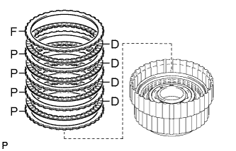
INSTALL NO. 3 CLUTCH DISC SET
-
Install the 4 plates, 4 discs and flange to the overdrive direct clutch drum.
Install in order P - D - P - D - P - D - P - D - F Tech Tips
P = Plate
D = Disc
F = Flange
Note
Before assembling new discs, soak them in ATF for at least 2 hours.
-
Temporarily install the snap ring.
-
Using a dial indicator, measure the moving distance (distance A) of the clutch flange at both ends across the diameter while blowing compressed air (196 kPa, 2.0 kgf*cm2, 28 psi) from the oil hole as shown in the illustration. Then choose from the 7 flange thicknesses in the table so that the measured value is within the standard value.
Standard 0.6 to 0.9 mm (0.0236 to 0.0354 in.) Flange thickness Mark Thickness 0 3.95 to 4.05 mm (0.1555 to 0.1594 in.) 1 4.05 to 4.15 mm (0.1594 to 0.1634 in.) 2 4.15 to 4.25 mm (0.1634 to 0.1673 in.) 3 4.25 to 4.35 mm (0.1673 to 0.1713 in.) 4 4.35 to 4.45 mm (0.1713 to 0.1752 in.) 5 4.45 to 4.55 mm (0.1752 to 0.1791 in.) 6 4.55 to 4.65 mm (0.1791 to 0.1831 in.) -
Temporarily remove the snap ring, attach the selected flange and restore the snap ring.
-
-
INSTALL FRONT PLANETARY GEAR ASSEMBLY
-
Install the front planetary sun gear.
-
Coat 2 new oil seal rings with ATF, and install them to the planetary gear.
Note
Do not expand the ring ends excessively.
-
Coat 3 new oil seal rings with ATF, and install them to the planetary gear.
Note
Do not expand the ring ends excessively.
-
Install the planetary carrier thrust washer to the planetary gear.
Note
Use a small amount of MP grease to make the thrust washer stay securely in place.
-
Assemble the front planetary gear assembly with the front planetary sun gear to the overdrive and reverse multiple disc clutch assembly.
-
-
SELECT NO. 1 BRAKE FLANGE
-
Measure length A (from the step of the oil pump installation surface of the transmission case to the step of the No. 1 brake flange installation surface) in the illustration. *1
Standard 59.77 to 60.03 mm (2.3531 to 2.3634 in.) -
Measure length B (from the flange face of the oil pump assembly to the tip of the No. 1 brake piston) in the illustration. *2
Standard 34.636 to 34.964 mm (1.3636 to 1.3765 in.) -
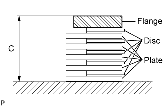
Assemble the 5 brake plates, 5 brake discs, and brake flange, and measure length C in the illustration. *3
Standard 23.84 to 24.36 mm (0.9386 to 0.9591 in.) -
Choose a No. 1 brake flange so that the value of measured length A minus lengths B and C (from steps *1, *2, *3) is 0.75 to 1.05 mm (0.0295 to 0.0413 in.).
Flange thickness Mark Thickness 0 4.45 to 4.55 mm (0.1752 to 0.1791 in.) 1 4.55 to 4.65 mm (0.1791 to 0.1831 in.) 2 4.65 to 4.75 mm (0.1831 to 0.1870 in.) 3 4.75 to 4.85 mm (0.1870 to 0.1909 in.) 4 4.85 to 4.95 mm (0.1909 to 0.1949 in.) 5 4.95 to 5.05 mm (0.1949 to 0.1988 in.) 6 5.05 to 5.15 mm (0.1988 to 0.2028 in.) 7 5.15 to 5.25 mm (0.2028 to 0.2067 in.) 8 5.25 to 5.35 mm (0.2067 to 0.2106 in.)
-
-
INSTALL OVERDRIVE AND REVERSE MULTIPLE DISC CLUTCH ASSEMBLY WITH FRONT PLANETARY GEAR ASSEMBLY
-
Install the thrust bearing race, thrust needle bearing, overdrive and reverse multiple disc clutch assembly with front planetary gear assembly to the transmission case.
Standard bearing and race diameter Item Inside Outside Race 44.0 mm (1.732 in.) 62.0 mm (2.441 in.) Bearing 36.2 mm (1.425 in.) 58.2 mm (2.291 in.) Note
-
Before installing the overdrive and reverse multiple clutch, apply ATF to the No. 3 clutch drum bush's sliding surfaces. After the installation, check that the No. 3 clutch drum rotates smoothly.
-
Use a small amount of MP grease to make the thrust bearing and thrust bearing race stay securely in place.
-
-
-
INSTALL NO. 1 BRAKE DISC SET
-
Install the selected flange, 5 discs and 5 plates to the transmission case.
Install in order F - D - P - D - P - D - P - D - P - D - P Tech Tips
F = Flange
D = Disc
P = Plate
Note
Before assembling new discs, soak them in ATF for at least 2 hours.
-
-
INSTALL OIL PUMP ASSEMBLY
-
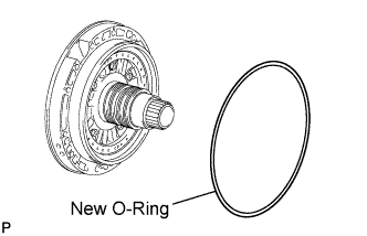
Coat a new O-ring with ATF, and install it to the oil pump.
-
Place the oil pump through the input shaft, and align the bolt holes of the oil pump with the transmission case.
-
Hold the input shaft, and lightly press the oil pump body to slide the oil seal rings into the No. 3 clutch drum.
-
Install the 11 bolts.
- Torque:
- 21 N*m { 214 kgf*cm, 15 ft.*lbf }
Note
-
Make sure to apply seal packing to the flanges of the bolts.
Seal packing Toyota Genuine Seal Packing 1281, Three Bond 1281 or equivalent -
Do not allow seal packing to contact the bolts' threads.
-
During installation, do not allow oil to contact the bolts or the surface of the oil pump body.
-
-
INSPECT INDIVIDUAL PISTON OPERATION
-
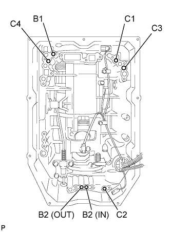
Check the operating sound while applying compressed air into the oil holes indicated in the illustration.
Tech Tips
C1 = Forward multiple clutch
C2 = No. 2 clutch
C3 = No. 3 clutch
C4 = Reverse clutch
B1 = No. 1 brake
B2 = No. 2 brake
-
-
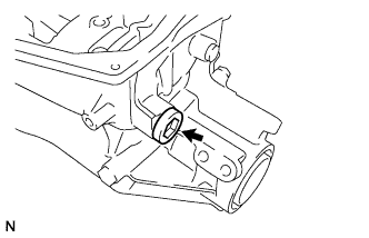
INSTALL MANUAL VALVE LEVER SHAFT OIL SEAL
-
Using SST and a hammer, tap in a new oil seal.
- SST
- 09350-30020 ( 09350-07110 )
Standard depth 0 +/-0.3 mm (0 +/-0.012 in.) -
Coat the lip of the oil seal with MP grease.
-
-
INSTALL MANUAL VALVE LEVER SUB-ASSEMBLY
-
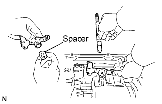
Install a new spacer to the manual valve lever.
-
Install the manual valve lever shaft to the transmission case through the manual valve lever.
-
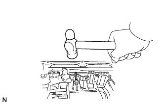
Using a hammer, tap in a new spring pin.
-
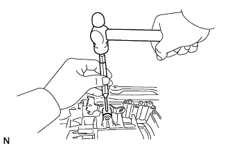
Align the manual valve lever indentation with the spacer hole, and stake them together with a punch.
-
Make sure that the shaft rotates smoothly.
-
-
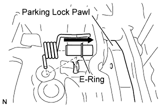
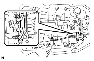
INSTALL PARKING LOCK PAWL SHAFT
-
Install the E-ring to the shaft.
-
Install the parking lock pawl, shaft and spring.
-
-
INSTALL PARKING LOCK ROD SUB-ASSEMBLY
-
Connect the parking lock rod to the manual valve lever.
-
-
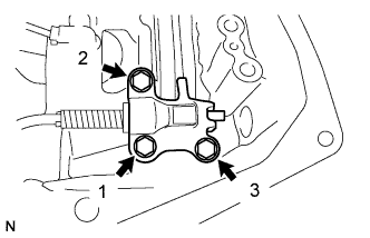
INSTALL PARKING LOCK PAWL BRACKET
-
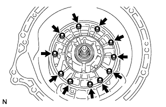
Place the parking lock pawl bracket onto the transmission case. Loosely install the 3 bolts, and then tighten them in the order shown in the illustration.
- Torque:
- 18 N*m { 184 kgf*cm, 13 ft.*lbf }
-
Shift the manual valve lever to the P position, and confirm that the output shaft is correctly locked up by the lock pawl.
-
-
INSTALL AUTOMATIC TRANSMISSION CASE PLUG
-
Coat a new O-ring with ATF, and install it to the case plug.
-
Install the case plug to the transmission case.
- Torque:
- 80 N*m { 816 kgf*cm, 59 ft.*lbf }
-
-
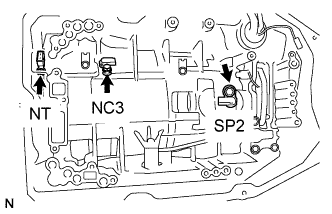
INSTALL SPEED SENSOR
-
Coat a new O-ring with ATF and install it to the speed sensor NT .
-
Using a T30 ''TORX'' wrench, install the sensor NT with the bolt.
- Torque:
- 6.8 N*m { 69 kgf*cm, 60 in.*lbf }
-
Install the speed sensor SP2 and NC3 with the 2 bolts.
- Torque:
- 5.4 N*m { 55 kgf*cm, 48 in.*lbf }
-
-
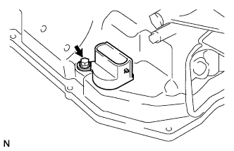
INSTALL TRANSMISSION WIRE
-
Coat a new O-ring with ATF and install it to the transmission wire connector.
-
Install the transmission wire.
-
Install the bolt.
- Torque:
- 5.4 N*m { 55 kgf*cm, 48 in.*lbf }
-
Coat a new O-ring with ATF and install it to the speed sensor NT.
-
Connect the 3 speed sensor connectors.
-
-
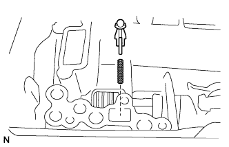
INSTALL CHECK BALL BODY
-
Install the spring and check ball body.
-
-
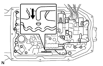
INSTALL TRANSMISSION VALVE BODY ASSEMBLY
-
Align the groove of the manual valve lever with the pin of the manual valve and install the pin.
-
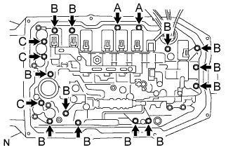
Install the 17 bolts.
- Torque:
- 11 N*m { 112 kgf*cm, 8 ft.*lbf }
Tech Tips
Each bolt length is indicated below.
Bolt length 21 mm (0.83 in.) for bolt A 31 mm (1.22 in.) for bolt B 64 mm (2.52 in.) for bolt C -
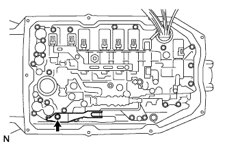
Install the detent spring and detent cover with the bolt.
- Torque:
- 10 N*m { 102 kgf*cm, 7 ft.*lbf }
Note
Make sure to install the detent spring so that its roller is perpendicularly at the center of the manual valve lever.
-
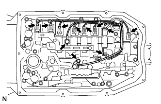
Connect the 8 connectors to the solenoid valves.
-
Coat a new O-ring with ATF and install it to the ATF temperature sensor.
-
Install the ATF temperature sensor and lock plate with the bolt.
- Torque:
- 10 N*m { 102 kgf*cm, 7 ft.*lbf }
-
-
INSTALL VALVE BODY OIL STRAINER ASSEMBLY

-
Coat a new O-ring with ATF and install it to the oil strainer.
Note
Ensure that the O-ring is not twisted or pinched.
-
Install the oil strainer to the valve body with the 4 bolts.
- Torque:
- 11 N*m { 112 kgf*cm, 8 ft.*lbf }
-
-
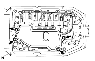
INSTALL AUTOMATIC TRANSMISSION OIL PAN SUB-ASSEMBLY
-
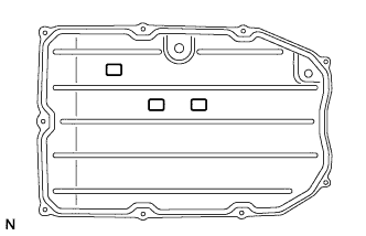
Install the 3 magnets to the oil pan.
-
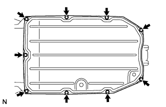
Install a new gasket and the oil pan to the transmission case with the 9 bolts.
- Torque:
- 7.3 N*m { 74 kgf*cm, 64 in.*lbf }
Note
-
-
Make sure that there is no oil or foreign matter on the gasket seal surface and oil pan contact surface.
-
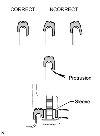
Install the gasket so that there is no slack in the gasket, and that the seal surface's entire circumference is level.
-
Make sure that the 9 gasket drop prevention protrusions are set on the oil pan.
-
When tightening the oil pan, make sure that the gasket is not pinched between the gasket tightening area's sleeve and the transmission's seal surface.
-
-
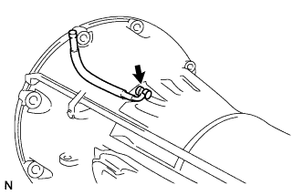
INSTALL NO. 1 BREATHER PLUG
-
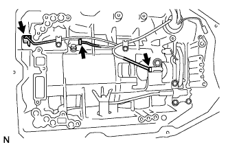
INSTALL OIL COOLER TUBE UNION
-
Coat 2 new O-rings with ATF, and install them to the unions.
-
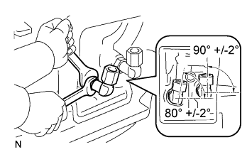
Install the unions as shown in the illustration.
- Torque:
- 29 N*m { 296 kgf*cm, 21 ft.*lbf }
-
-
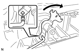
INSTALL PARK/NEUTRAL POSITION SWITCH ASSEMBLY
Tech Tips
Make sure that the manual valve lever shaft has not been rotated prior to installing the park/neutral position switch as the detent spring may become detached from the manual valve lever shaft.
-
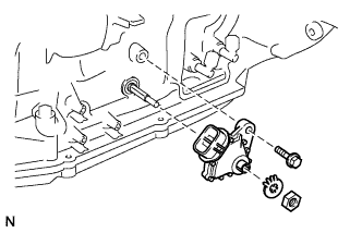
Install the park/neutral position switch onto the manual valve lever shaft, and temporarily install the bolt.
-
Install a new lock washer with the nut.
- Torque:
- 6.9 N*m { 70 kgf*cm, 61 in.*lbf }
-
Temporarily install the control shaft lever.
-
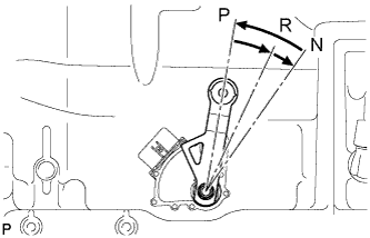
Turn the control shaft lever counterclockwise until it stops, and turn it clockwise 2 notches to set it to the N position.
-
Remove the control shaft lever.
-
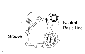
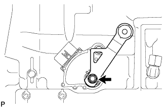
Align the groove with the neutral basic line.
- Torque:
- 13 N*m { 133 kgf*cm, 10 ft.*lbf }
-
Hold the switch in this position and tighten the bolt.
- Torque:
- 13 N*m { 133 kgf*cm, 10 ft.*lbf }
-
Using a screwdriver, bend the tabs of the lock washer.
Tech Tips
Bend at least 2 washer tabs.
-
-
INSTALL TRANSMISSION CONTROL SHAFT LEVER RH
-
Install the transmission control shaft lever with the nut.
- Torque:
- 16 N*m { 163 kgf*cm, 12 ft.*lbf }
-