COMBINATION SWITCH REMOVAL

Tech Tips
-
Use the same procedure for the RHD and LHD sides.
-
The procedure listed below is for the LHD sides.
-
REMOVE SHIFT LEVER KNOB SUB-ASSEMBLY
-
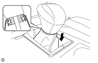
Lower the shift lever boot and disconnect it from the shift lever knob sub-assembly.
-
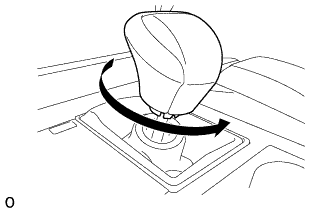
Twist the shift lever knob sub-assembly in the direction indicated by the arrow and remove it.
-
-
REMOVE INSTRUMENT PANEL FINISH PANEL END LH
-
Pull the front part of the instrument panel finish panel end LH to detach the 6 clips.
-
Pull the instrument panel finish panel end LH to detach 3 clips and remove the instrument panel finish panel end LH.
-
-
REMOVE INSTRUMENT PANEL FINISH PANEL END RH
Tech Tips
Use the same procedure described for the LH side.
-
REMOVE NO. 3 BOX PANEL
-
Detach the 4 claws and remove the No. 3 box panel.
-
-
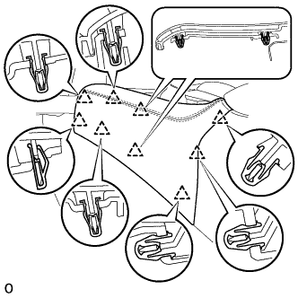
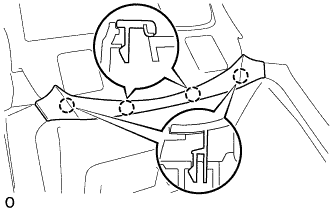
REMOVE REAR CONSOLE UPPER PANEL SUB-ASSEMBLY
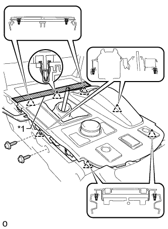
Text in Illustration *1 Protective Tape
-
Apply protective tape as shown in the illustration.
-
Move the shift lever to N.
-
Remove the 2 screws.
-
Detach the 6 clips and remove the upper rear console panel sub-assembly.
-
Disconnect each connector and each wire harness clamp.
-
-
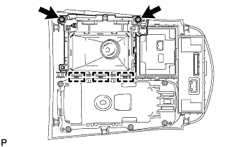
REMOVE SHIFT POSITION INDICATOR
-
Remove the 2 screws and detach the 3 hooks. Then remove the shift position indicator from the rear upper console panel sub-assembly.
-
-
REMOVE COMBINATION SWITCH
-
Disconnect the connector.
-
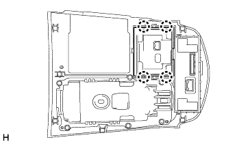
Detach the 4 claws and remove the combination switch from the rear upper console panel sub-assembly.
-