AUTOMATIC TRANSMISSION SYSTEM TCM Power Source Circuit
DESCRIPTION
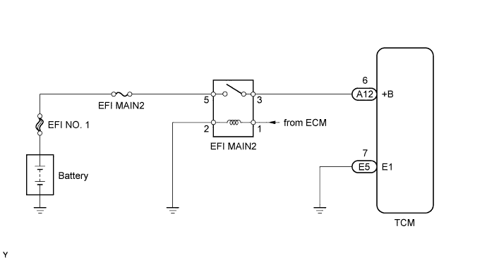
When the engine switch is turned on (IG), voltage from the ECM's MREL terminal is applied to the EFI MAIN 2 relay. This causes the contacts of the EFI MAIN 2 relay to close, which supplies power to terminal +B of the TCM.
WIRING DIAGRAM
INSPECTION PROCEDURE
PROCEDURE
-
CHECK TCM (POWER SOURCE, GROUND)
-
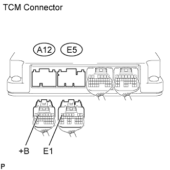
Disconnect the A12 and E5 TCM connectors.
-
Turn the engine switch on (IG).
-
Measure the voltage of the wire harness side connectors.
Standard voltage Tester Connection Switch Condition Specified Condition A12-6 (+B) - E5-7 (E1) Engine switch on (IG) 11 to 14 V -
Turn the engine switch off.
-
Measure the resistance of the wire harness side connector.
Standard resistance Tester Connection Condition Specified Condition E5-7 (E1) - Body ground Always Below 1 Ω Result Result Proceed to NG A OK (for 1UR-FSE) B OK (for 1UR-FE) C
B 
GO TO ECM POWER SOURCE CIRCUIT (ENGINE CONTROL SYSTEM / SFI SYSTEM) Click here
C
GO TO ECM POWER SOURCE CIRCUIT (ENGINE CONTROL SYSTEM / SFI SYSTEM) Click here
A 
CHECK HARNESS AND CONNECTOR (TCM - EFI MAIN NO. 2 RELAY, GROUND)
-