AUTOMATIC TRANSMISSION SYSTEM, Diagnostic DTC:P0873

| DTC Code | DTC Name |
|---|---|
| P0873 | Transmission Fluid Pressure Sensor / Switch "C" Circuit High |
DESCRIPTION
The oil pressure switch, which is built into the valve body, detects the fluid pressure of the SL1 fluid pressure circuit. If shift solenoid valve SL1 is stuck on, P0873 is output.
| DTC Code | DTC Detection Condition
|
Trouble Area |
|---|---|---|
| P0873 |
|
|
WIRING DIAGRAM
Refer to DTC P0872 Click here.
INSPECTION PROCEDURE
PROCEDURE
-
CHECK DTC OUTPUT (IN ADDITION TO DTC P0746 AND P0873)
-
Connect the intelligent tester to the DLC3.
-
Turn the engine switch on (IG).
-
Turn the intelligent tester on.
-
Enter the following menus: Powertrain / ECT / DTC.
-
Read the DTCs using the intelligent tester.
Result Display (DTC output) Proceed to Only P0746 and P0873 are output A P0746, P0873 and other DTCs are output B Tech Tips
If any other codes besides P0746 and P0873 are output, perform troubleshooting for those DTCs first.
B 
GO TO DTC CHART Click here
A 
-
-
CHECK OIL PRESSURE SWITCH CIRCUIT
-

Measure the resistance according to the value(s) in the table below.
Standard Resistance Tester Connection Condition Specified Condition E6-25 (TPS1) - Body ground Always 10 kΩ or higher Tech Tips
Do not disconnect the connectors of the TCM.
NG 
READ VALUE USING DATA LIST (TPS 1 SW SIGNAL) Click here
OK
-
-
INSPECT SHIFT SOLENOID VALVE SL1
-
Remove shift solenoid valve SL1 Click here.
-
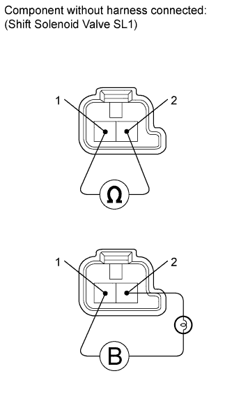
Measure the resistance according to the value(s) in the table below.
Standard Resistance Tester Connection Condition Specified Condition Terminal 1 of shift solenoid valve SL1 - Terminal 2 20°C (68°F) 5.0 to 5.6 Ω -
Connect the battery's positive (+) lead with a 21 W bulb to terminal 2 and the negative (-) lead to terminal 1 of the solenoid valve connector. Then check that the valve moves and makes an operating noise.
OK Valve moves and makes operating noise.
NG
REPLACE SHIFT SOLENOID VALVE SL1 Click here
OK
-
-
INSPECT TRANSMISSION VALVE BODY ASSEMBLY
-
Check the transmission valve body assembly Click here.
OK There are no foreign objects on any valve.
NG
REPAIR OR REPLACE TRANSMISSION VALVE BODY ASSEMBLY Click here
OK
-
-
INSPECT TORQUE CONVERTER CLUTCH ASSEMBLY
-
Check the torque converter clutch assembly Click here.
OK The torque converter clutch operates normally.
NG
REPLACE TORQUE CONVERTER CLUTCH ASSEMBLY Click here
OK 
REPAIR OR REPLACE AUTOMATIC TRANSMISSION ASSEMBLY Click here
-
-
READ VALUE USING DATA LIST (TPS 1 SW SIGNAL)
-
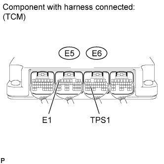
Connect terminals TPS1 and E1 of the E5 and E6 TCM connectors.
Tech Tips
Before connecting the terminals, do visual and contact pressure checks on the TCM connectors.
-
Connect the intelligent tester to the DLC3.
-
Turn the engine switch on (IG).
-
Turn the intelligent tester on.
-
Enter the following menus: Powertrain / ECT / Data List.
-
Read the value displayed on the intelligent tester.
Result Tester Display Proceed to TPS 1 Switch OFF A TPS 1 Switch ON B
B
CHECK HARNESS AND CONNECTOR (TRANSMISSION WIRE - TCM) Click here
A
-
-
REPLACE TCM
-
Replace the TCM Click here.
NEXT
PERFORM A/T CODE REGISTRATION Click here
-
-
CHECK HARNESS AND CONNECTOR (TRANSMISSION WIRE - TCM)
-
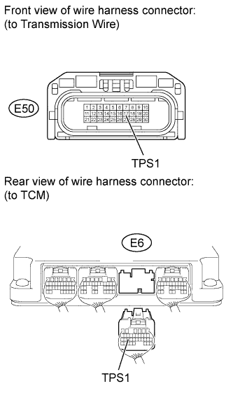
Disconnect the E50 transmission wire connector.
-
Disconnect the E6 TCM connector.
-
Measure the resistance according to the value(s) in the table below.
Standard Resistance Tester Connection Condition Specified Condition E50-17 (TPS1) - E6-25 (TPS1) Always Below 1 Ω E50-17 (TPS1) or E6-25 (TPS1) - Body ground Always 10 kΩ or higher
NG
REPAIR OR REPLACE HARNESS OR CONNECTOR
OK
-
-
INSPECT TRANSMISSION WIRE (OIL PRESSURE SWITCH)
-
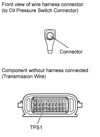
Disconnect the oil pressure switch connector.
-
Disconnect the E50 transmission wire connector.
-
Measure the resistance according to the value(s) in the table below.
Standard Resistance Tester Connection Condition Specified Condition Oil pressure switch connector - 17 (TPS1) Always Below 1 Ω Oil pressure switch connector or 17 (TPS1) - Body ground Always 10 kΩ or higher
NG
REPAIR OR REPLACE TRANSMISSION WIRE Click here
OK
REPLACE OIL PRESSURE SWITCH Click here
-