PARK / NEUTRAL POSITION SWITCH INSTALLATION

-
INSTALL PARK/NEUTRAL POSITION SWITCH ASSEMBLY
Tech Tips
Make sure that the manual valve lever shaft has not been rotated prior to installing the park/neutral position switch as the detent spring may become detached from the manual valve lever shaft.
-
Install the switch to the manual valve shaft.
-
Temporarily install the bolt.
-
Install a new lock washer with the nut.
- Torque:
- 6.9 N*m { 70 kgf*cm, 61 in.*lbf }
-
Temporarily install the transmission control shaft lever RH.
-
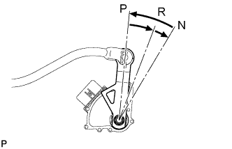
Turn the control shaft lever counterclockwise until it stops, and then turn it clockwise 2 notches to set it to the N position.
-
Remove the control shaft lever.
-
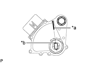
Text in Illustration *a Neutral Basic Line *b Groove Align the groove with the neutral basic line.
-
Hold the switch in this position and tighten the bolt.
- Torque:
- 13 N*m { 133 kgf*cm, 10 ft.*lbf }
-
Using a screwdriver, bend the tabs of the lock washer.
Tech Tips
Bend at least 2 washer tabs.
-
Install the transmission control shaft lever with the spring washer and nut.
- Torque:
- 16 N*m { 163 kgf*cm, 12 ft.*lbf }
-
Connect the switch connector.
-
-
CONNECT FLOOR SHIFT GEAR SHIFTING ROD SUB-ASSEMBLY
-
Temporarily connect the shifting rod to the connecting rod swivel with the nut.
Tech Tips
The nut will be tightened to a torque specification during the shift lever position adjustment procedure.
-
-
ADJUST SHIFT LEVER POSITION
-
INSPECT PARK/NEUTRAL POSITION SWITCH ASSEMBLY