AUTOMATIC TRANSMISSION SYSTEM, Diagnostic DTC:P0712, P0713

| DTC Code | DTC Name |
|---|---|
| P0712 | Transmission Fluid Temperature Sensor "A" Circuit Low Input |
| P0713 | Transmission Fluid Temperature Sensor "A" Circuit High Input |
DESCRIPTION
The transmission fluid temperature is detected using the Automatic Transmission Fluid (ATF) temperature sensor, which is built onto the valve body. Depending on the fluid temperature, a signal is input into the TCM.
The TCM applies a voltage to the temperature sensor through TCM terminal OIL.
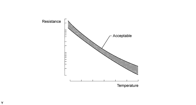
The sensor resistance changes with the ATF temperature. As the temperature becomes higher, the sensor resistance decreases.
One terminal of the sensor is grounded so that the sensor resistance decreases and the voltage decreases as the temperature becomes higher.
The TCM calculates the ATF temperature based on the voltage signal.
| DTC No. | DTC Detection Condition
|
Trouble Area |
|---|---|---|
| P0712 |
|
|
| P0713 |
|
|
MONITOR DESCRIPTION
The ATF temperature sensor converts ATF temperature to an electrical resistance value. Based on the resistance, the TCM determines the ATF temperature, and the TCM detects an open or short in the ATF temperature circuit. If the resistance value of the ATF temperature is less than 79 Ω*1 or more than 156 kΩ*2, the TCM interprets this as a fault in the ATF sensor or wiring. The TCM illuminates the MIL and stores a DTC.
Tech Tips
-
*1: 150°C (302°F) or more is indicated regardless of the actual ATF temperature.
-
*2: -40°C (-40°F) is indicated regardless of the actual ATF temperature.
-
The ATF temperature can be checked on the intelligent tester display.
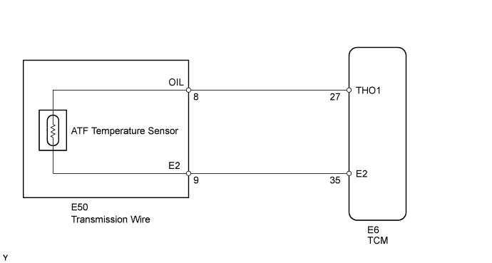
WIRING DIAGRAM
INSPECTION PROCEDURE
Tech Tips
Using the intelligent tester's Data List allows switch, sensor, actuator and other item values to be read without removing any parts. Reading the Data List early in troubleshooting is one way to save time.
Note
In the table below, the values listed under "Normal Condition" are reference values. Do not depend solely on these reference values when deciding whether a part is faulty or not.
-
Warm up the engine.
-
Turn the engine switch off.
-
Connect the intelligent tester to the DLC3.
-
Turn the engine switch on (IG).
-
Turn the intelligent tester ON.
-
Enter the following menus: Powertrain / ECT / Data List.
-
Follow the instructions on the tester and read the Data List.
| Tester Display | Measurement Item/Range | Normal Condition | Diagnostic Note |
|---|---|---|---|
| A/T Oil Temperature 1 | ATF temperature sensor value/ Min.: -40°C (-40°F) Max.: 215°C (419°F) |
|
If value is -40°C (-40°F) or 150°C (302°F), ATF temperature sensor circuit is open or short circuited |
Tech Tips
-
When DTC P0712 is output and the intelligent tester output is 150°C (302°F) or more, there is a short circuit.
-
When DTC P0713 is output and the intelligent tester output is -40°C (-40°F), there is an open circuit.
Measure the resistance between terminal OIL (OT) and the body ground.
| Temperature Displayed | Malfunction |
|---|---|
| -40°C (-40°F) | Open circuit |
| 150°C (302°F) or more | Short circuit |
Tech Tips
-
If a circuit related to the ATF temperature sensor becomes open, P0713 is set in approximately 0.5 seconds.
-
It is not necessary to inspect the circuit when P0711 is set.
PROCEDURE
-
CHECK HARNESS AND TRANSMISSION WIRE (TRANSMISSION WIRE - TCM, TRANSMISSION WIRE (ATF TEMPERATURE SENSOR))
-
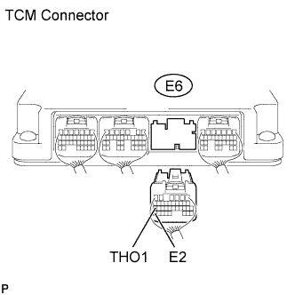
Disconnect the E6 TCM connector.
-
Measure the resistance of the wire harness side connector.
Standard resistance Tester Connection Condition Specified Condition E6-27 (THO1) - E6-35 (E2) ATF temperature 10°C (50°F) 5.8 to 7.1 kΩ E6-27 (THO1) - E6-35 (E2) ATF temperature 25°C (77°F) 2.5 to 4.5 kΩ E6-27 (THO1) - E6-35 (E2) ATF temperature 110°C (230°F) 231 to 263 Ω Tech Tips
The resistance value for the 25°C (77°F) ATF temperature condition is a reference value.
-
Measure the resistance of the wire harness side connector.
Standard resistance Tester Connection Condition Specified Condition E6-27 (THO1) - Body ground Always 10 kΩ or higher E6-35 (E2) - Body ground Always 10 kΩ or higher E6-27 (THO1) or E6-35 (E2) - Body ground Always 10 kΩ or higher
NG 
CHECK HARNESS AND CONNECTOR (TRANSMISSION WIRE - TCM) Click here
OK 
-
-
REPLACE TCM
-
Replace the TCM Click here.
NEXT 
PERFORM AT REGISTRATION Click here
-
-
CHECK HARNESS AND CONNECTOR (TRANSMISSION WIRE - TCM)
-
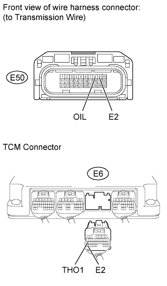
Disconnect the E50 transmission wire connector.
-
Disconnect the E6 TCM connector.
-
Measure the resistance of the wire harness side connectors.
Standard resistance Tester Connection Condition Specified Condition E50-8 (OIL) - E6-27 (THO1) Always Below 1 Ω E50-9 (E2) - E6-35 (E2) Always Below 1 Ω E50-8 (OIL) or E6-27 (THO1) - Body ground Always 10 kΩ or higher E50-9 (E2) or E6-35 (E2) - Body ground Always 10 kΩ or higher
NG 
REPAIR OR REPLACE HARNESS OR CONNECTOR
OK
REPAIR OR REPLACE TRANSMISSION WIRE Click here
-