ENTRY AND START SYSTEM Engine does not Start
DESCRIPTION
-
ENGINE START SYSTEM OPERATION
-
When the engine switch is pressed with the brake pedal depressed and shift lever in P or N, the main body ECU determines that it is an engine start request.
-
The certification ECU and other ECUs perform key verification via the LIN communication line. The engine switch indicator light illuminates in green.
-
The main body ECU activates the D-ACC, D-IG1-1 and IG2 relays.
-
The certification ECU outputs a steering UNLOCK signal. The signal is sent to the steering lock ECU via the LIN communication line.
-
The main body ECU sends an engine start request signal to the ECM.
-
The ECM sends an ACC cut request signal to the main body ECU.
-
The ECM and main body ECU activate the ST CUT/IGCT2 relay.
-
The main body ECU deactivates the D-ACC relay until the ECU detects an engine start.
-
The ECU reactivates the D-ACC relay and turns off the engine switch indicator light.
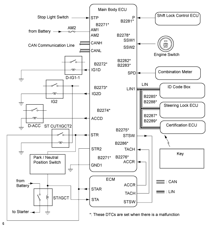
Symbols of main body ECU Signals SSW1/SSW2 Engine switch on (ACC, IG) signal ACCD D-ACC relay operation signal IG2D IG2 relay operation signal STR2 ST CUT/IGCT2 relay operation signal STR Park / neutral position switch signal STP Stop light switch signal TACH Engine start detection signal STSW Starter activation request signal ACCR ACC cut request signal
-
WIRING DIAGRAM
Refer to the CRANKING HOLDING FUNCTION CIRCUIT Click here.
INSPECTION PROCEDURE
PROCEDURE
-
CHECK WHETHER ENGINE STARTS AFTER STEERING LOCK INITIALIZATION
-
Open and close the driver door when the engine switch is off.
-
Check that the engine starts.
OK Engine starts. Tech Tips
After the battery runs out, the engine may not start if the steering lock ECU has not been initialized (lock / unlock may not be recorded) through the procedure described above.
OK 
SYSTEM OK
NG 
-
-
CHECK WHETHER DTC OUTPUT RECURS (MAIN BODY ECU AND CERTIFICATION ECU)
-
Clear the DTCs Click here.
Tech Tips
After all DTCs are cleared, check if the trouble occurs again 5 seconds after the engine switch is turned on (IG).
-
Check for DTCs again.
OK No DTC is output.
NG
GO TO DTC CHART Click here
OK
-
-
CHECK ENGINE SWITCH (SWITCH CONDITION)
-
Ensure the key is inside the cabin.
-
With the brake pedal released, check that the power source mode changes as shown below each time the engine switch is pushed.
OK off → on (ACC) → on (IG) → off
NG
GO TO POWER SOURCE MODE DOES NOT CHANGE Click here
OK
-
-
CHECK BASIC FUNCTION
-
Ensure that there is fuel in the fuel tank and the key is inside the cabin.
-
Depress the brake pedal with the shift lever in P or N, and keep depressing the pedal.
-
Check that the engine cranks when the engine switch is pressed.
OK Engine cranks.
OK 
READ VALUE USING INTELLIGENT TESTER (ENGINE START REQUEST) Click here
NG
-
-
READ VALUE USING INTELLIGENT TESTER (PARK / NEUTRAL POSITION SWITCH)
-
Use the Data List to check if the park / neutral position switch is functioning properly.
Main Body Tester Display Measurement Item/Range Normal Condition Diagnostic Note Neutral SW / Clutch SW Park / neutral position switch/ON or OFF ON: Shift lever in P or N
OFF: Shift lever in R or D
- OK When the shift lever is in P or N, ON is displayed on the tester.
NG
REPAIR OR REPLACE PARK / NEUTRAL POSITION SWITCH Click here
OK
-
-
READ VALUE USING INTELLIGENT TESTER (STOP LIGHT SW)
-
Use the Data List to check if the stop light switch is functioning properly.
Main Body Tester Display Measurement Item/Range Normal Condition Diagnostic Note Stop Light SW Stop Light switch/ON or OFF ON: Brake pedal is depressed
OFF: Brake pedal is released
- OK When the brake pedal is depressed, ON is displayed on the tester.
NG
REPAIR OR REPLACE STOP LIGHT SWITCH ASSEMBLY
OK
-
-
CHECK STEERING LOCK SYSTEM
-
When the engine switch is on (ACC), check that the steering lock can be released.
OK Steering lock can be released.
NG
GO TO STEERING LOCK SYSTEM Click here
OK
-
-
INSPECT MAIN BODY ECU
-
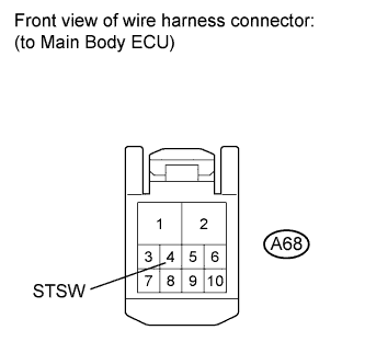
Disconnect the A68 main body ECU connector.
-
Depress the brake pedal with the shift lever in P or N, and keep depressing the pedal.
-
Measure the voltage according to the value(s) in the table below.
Standard voltage Tester Connection Condition Specified Condition A68-4 (STSW) - Body ground When the engine cranks by pressing the engine switch. 11 to 14 V
NG
GO TO SFI SYSTEM (CRANKING HOLDING FUNCTION CIRCUIT) Click here
OK 
REPLACE MAIN BODY ECU
-
-
READ VALUE USING INTELLIGENT TESTER (ENGINE START REQUEST)
-
Use the Data List to check if the engine start request is functioning properly.
Entry & Start Tester Display Measurement Item/Range Normal Condition Diagnostic Note Engine Start Request Starter request signal/Yes or No YES: ID code box receives immobiliser unset signal
NO: ID code box does not receive immobiliser unset signal
- OK When ID code box receives immobiliser unset signal, YES is displayed on tester.
NG
REPLACE CERTIFICATION ECU
OK
REPLACE ID CODE BOX
-