ENTRY AND START SYSTEM Power Source Mode does not Change
DESCRIPTION
When the certification ECU has detected the key inside the cabin before the brake pedal is depressed, the power source mode can be changed in the following order sequentially by pressing the engine switch: off → on (ACC) → on (IG) → off.
When one of the DTCs shown in the illustration below is detected, troubleshoot the DTC(s) by following the troubleshooting procedure relevant to the DTC(s). If the power source mode still cannot be changed normally, despite troubleshooting, one of the following may have occurred:
-
The LIN communication line is malfunctioning.
-
The certification ECU has determined that no key is inside the cabin.
-
The engine switch is malfunctioning.
-
The main body ECU is malfunctioning.
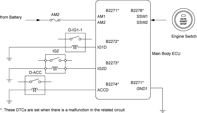
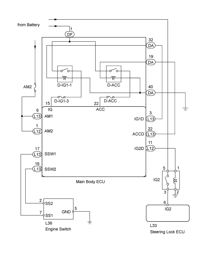
WIRING DIAGRAM
INSPECTION PROCEDURE
Tech Tips
If the vehicle is in key cancel mode, change to normal mode Click here.
PROCEDURE
-
CHECK WHETHER DTC OUTPUT RECURS
-
Clear the DTCs Click here.
Tech Tips
After all DTCs are cleared, check if the trouble occurs again 5 seconds after the engine switch is turned on (IG).
-
Check for DTCs again.
OK No DTC is output.
NG 
GO TO DTC CHART Click here
OK 
-
-
CHECK ENGINE SWITCH (SWITCH CONDITION)
-
Ensure the key is inside the cabin.
-
Check that the engine switch indicator illuminates in green when the shift lever is in P or N and the brake pedal is depressed.
OK Engine switch indicator illuminates in green.
NG
GO TO ROOM OSCILLATOR DOES NOT RECOGNIZE KEY Click here
OK
-
-
READ VALUE USING INTELLIGENT TESTER (RELAY MONITOR)
-
Use the Data List to check if the relay monitor is functioning properly.
Main Body Tester Display Measurement Item/Range Normal Condition Diagnostic Note IG1 Relay Monitor (Outside) D-IG1-1 relay outer relay monitor/ON or OFF ON: Engine switch on (IG)
OFF: Engine switch off
- IG1 Relay Monitor (Inside) D-IG1-1 relay inner relay monitor/ON or OFF ON: Engine switch on (IG)
OFF: Engine switch off
- IG2 Relay Monitor (Outside) IG2 outer relay monitor/ON or OFF ON: Engine switch on (IG)
OFF: Engine switch off
- IG2 Relay Monitor (Inside) IG2 inner relay monitor/ON or OFF ON: Engine switch on (IG)
OFF: Engine switch off
- ACC Relay Monitor D-ACC relay monitor/ON or OFF ON: Engine switch on (IG)
OFF: Engine switch off
- OK ON is displayed on the tester screen.
NG 
INSPECT ENGINE SWITCH Click here
OK
-
-
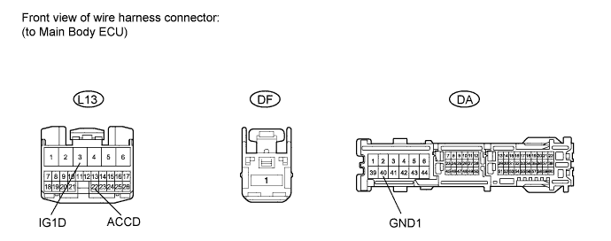
CHECK HARNESS AND CONNECTOR (MAIN BODY ECU)
-
Disconnect the L13, DF and DA main body ECU connectors.
-
Measure the resistance and voltage according to the value(s) in the table below.
Standard resistance Tester Connection Condition Specified Condition L13-3 (IG1D) - DA-32 Always Below 1 Ω L13-3 (IG1D) or DA-32 - Body ground Always 10 kΩ or higher L13-22 (ACCD) - DA-19 Always Below 1 Ω L13-22 (ACCD) or DA-19 - Body ground Always 10 kΩ or higher DA-40 - Body ground Always Below 1 Ω Standard voltage Tester Connection Condition Specified Condition DF-1 - Body ground Always 11 to 14 V
NG
REPAIR OR REPLACE HARNESS OR CONNECTOR
OK
-
-
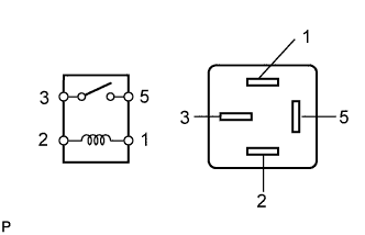
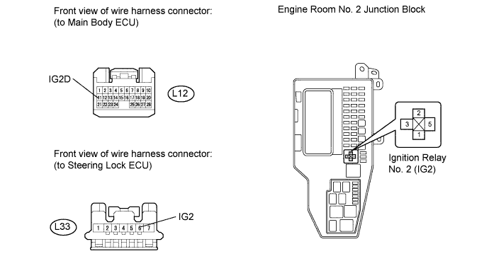
INSPECT IGNITION RELAY NO.2 (IG2)
-
Remove the ignition relay No. 2 from the engine room No. 2 junction block.
-
Measure the resistance according to the value(s) in the table below.
Standard resistance Tester Connection Condition Specified Condition 3 - 5 When battery voltage is not applied to terminals 1 and 2 10 kΩ or higher 3 - 5 When battery voltage is applied to terminals 1 and 2 Below 1 Ω
NG
REPLACE IGNITION RELAY NO.2 (IG2)
OK
-
-
CHECK HARNESS AND CONNECTOR (NO. 2 RELAY BLOCK - MAIN BODY ECU AND STEERING LOCK ECU)
-
Remove the IG2 relay from the engine room No. 2 junction block.
-
Disconnect the L12 main body ECU connector.
-
Disconnect the L33 steering lock ECU connector.
-
Measure the resistance according to the value(s) in the table below.
Standard resistance Tester Connection Condition Specified Condition L12-11 (IG2D) - Relay block ignition relay No. 2 terminal 1 Always Below 1 Ω L12-11 (IG2D) or Relay block ignition relay No. 2 terminal 1 - Body ground Always 10 kΩ or higher Relay block ignition relay No. 2 terminal 2 - Body ground Always Below 1 Ω L33-6 (IG2) - Relay block ignition relay No. 2 terminal 3 Always Below 1 Ω L33-6 (IG2) or Relay block ignition relay No. 2 terminal 3 - Body ground Always 10 kΩ or higher
NG
REPAIR OR REPLACE HARNESS OR CONNECTOR
OK 
REPLACE MAIN BODY ECU
-
-
INSPECT ENGINE SWITCH
-
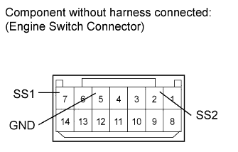
Remove the engine switch Click here.
-
Measure the resistance according to the value(s) in the table below.
Standard resistance Tester Connection Switch Condition Specified Condition 7 (SS1) - 5 (GND) Pushed Below 1 Ω 2 (SS2) - 5 (GND) Pushed Below 1 Ω 7 (SS1) - 5 (GND) Not pushed 10 kΩ or higher 2 (SS2) - 5 (GND) Not pushed 10 kΩ or higher
NG
REPLACE ENGINE SWITCH Click here
OK
-
-
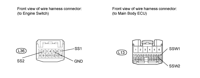
CHECK HARNESS AND CONNECTOR (MAIN BODY ECU - ENGINE SWITCH)
-
Disconnect the L13 main body ECU connector.
-
Disconnect the L36 engine switch connector.
-
Measure the resistance according to the value(s) in the table below.
Standard resistance Tester Connection Condition Specified Condition L36-7 (SS1) - L13-17 (SSW1) Always Below 1 Ω L36-2 (SS2) - L13-16 (SSW2) Always Below 1 Ω L36-5 (GND) - Body ground Always Below 1 Ω L36-7 (SS1) or L13-17 (SSW1) - Body ground Always 10 kΩ or higher L36-2 (SS2) or L13-16 (SSW2) - Body ground Always 10 kΩ or higher
NG
REPAIR OR REPLACE HARNESS OR CONNECTOR
OK
-
-
INSPECT FUSE (AM2)
-
Remove the AM2 fuse from the passenger side junction block.
-
Check the resistance of the fuse.
Standard resistance Tester Connection Condition Specified Condition AM2 fuse Always Below 1 Ω
NG
REPLACE FUSE (AM2)
OK
-
-
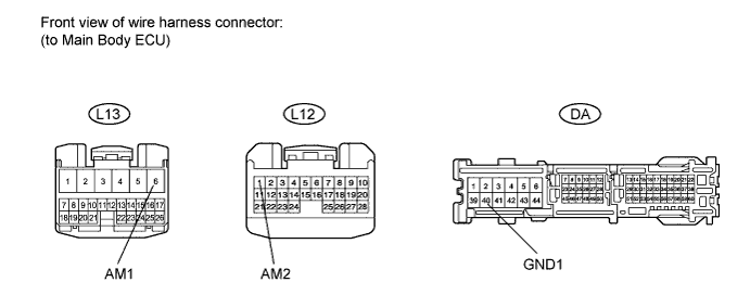
CHECK HARNESS AND CONNECTOR (MAIN BODY ECU - BATTERY AND BODY GROUND)
-
Disconnect the L13, L12 and DA main body ECU connectors.
-
Measure the voltage and resistance according to the value(s) in the table below.
Standard voltage Tester Connection Condition Specified Condition L13-6 (AM1) - Body ground Always 11 to 14 V L12-1 (AM2) - Body ground Always 11 to 14 V Standard resistance Tester Connection Condition Specified Condition DA-1 (GND1) - Body ground Always Below 1 Ω
NG
REPAIR OR REPLACE HARNESS OR CONNECTOR
OK
REPLACE MAIN BODY ECU
-