IGNITION COIL AND SPARK PLUG INSTALLATION

-
INSTALL SPARK PLUG
-
Using a 16 mm plug wrench, install the 8 spark plugs.
- Torque:
- 21 N*m { 214 kgf*cm, 15 ft.*lbf }
-
-
INSTALL IGNITION COIL ASSEMBLY
-
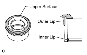
Perform a visual inspection of the spark plug tube gasket.
Standard Area Specified condition Upper surface No scratches or deformation Outer lip No scratches or deformation Inner lip No scratches If the result is not as specified, replace the spark plug tube gasket.
-
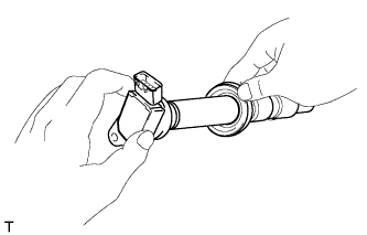
Slide the spark plug tube gasket onto the ignition coil assembly as shown in the illustration.
-
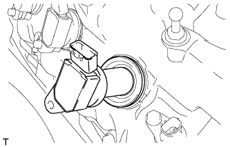
After installing the spark plug tube gasket, firmly insert the ignition coil assembly as shown in the illustration.
-
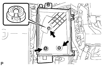
Install the 8 bolts.
- Torque:
- 10 N*m { 102 kgf*cm, 7 ft.*lbf }
-
Connect the 8 ignition coil assembly connectors.
-
-
INSTALL NO. 6 ENGINE COVER SUB-ASSEMBLY (for AWD)
-
Install the No. 6 engine cover sub-assembly with the 2 nuts.
- Torque:
- 15 N*m { 153 kgf*cm, 11 ft.*lbf }
-
-
INSTALL NO. 5 ENGINE COVER SUB-ASSEMBLY (for AWD)
-
Install the No. 5 engine cover sub-assembly with the 2 nuts.
- Torque:
- 15 N*m { 153 kgf*cm, 11 ft.*lbf }
-
-
INSTALL NO. 2 ENGINE COVER (for LHD with 2WD)
-
Install the No. 2 engine cover with the 4 nuts.
- Torque:
- 21 N*m { 214 kgf*cm, 15 ft.*lbf }
-
-
INSTALL ENGINE OIL LEVEL DIPSTICK GUIDE
-
Apply a light coat of engine oil to a new O-ring.
-
Install the O-ring to the engine oil level dipstick guide.
-
Install the engine oil level dipstick guide with the 2 bolts.
- Torque:
- 10 N*m { 102 kgf*cm, 7 ft.*lbf }
-
Install the engine oil level dipstick.
-
-
CONNECT ENGINE WIRE
-
Install the engine wire to the No. 1 relay block with the nut.
- Torque:
- 13 N*m { 127 kgf*cm, 9 ft.*lbf }
-
Connect the 2 clamps.
-
Install the No. 1 relay block cover.
-
-
INSTALL BATTERY TRAY
-
Install the battery tray with the 3 bolts.
- Torque:
- 5.4 N*m { 55 kgf*cm, 47 in.*lbf }
-
-
INSTALL BATTERY
-
Install the battery.
-
Install the battery insulator.
-
Install the battery clamp with the nut.
- Torque:
- 5.4 N*m { 55 kgf*cm, 47 in.*lbf }
-
Connect the battery cable clamp.
-
Connect the cable to the positive (+) battery terminal.
- Torque:
- 5.4 N*m { 55 kgf*cm, 47 in.*lbf }
-
-
INSTALL SKID CONTROL ECU BRACKET (for LHD)
-
INSTALL SKID CONTROL ECU BRACKET (for RHD)
-
INSTALL AIR CLEANER ASSEMBLY RH
-
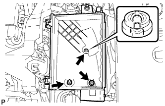
Install the air cleaner case RH with the 2 nuts and clip.
- Torque:
- 5.0 N*m { 51 kgf*cm, 44 in.*lbf }
-
Install the air cleaner filter element to the air cleaner case RH.
-
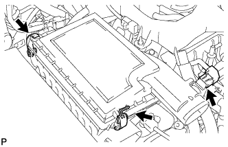
Install the air cleaner cap RH with the 2 clamps.
-
Connect the mass air flow meter connector.
-
-
INSTALL AIR CLEANER ASSEMBLY LH
-
Install the air cleaner case LH with the 2 nuts and clip.
- Torque:
- 5.0 N*m { 51 kgf*cm, 44 in.*lbf }
-
Install the air cleaner filter element to the air cleaner case LH.
-
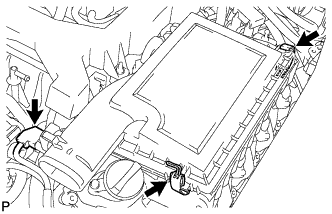
Install the air cleaner cap LH with the 2 clamps.
-
Connect the mass air flow meter connector.
-
-
INSTALL INTAKE AIR CONNECTOR PIPE
-
Install the intake air sound creator.
Tech Tips
Only perform this procedure when replacement of the intake air sound creator is necessary.
-
Install the intake air sound creator with the bolt and hose clamp.
- Torque:
- 2.0 N*m { 20 kgf*cm, 18 in.*lbf }
-
-
Align the protrusion of the intake air resonator with the cutout of the bracket and insert the protrusion.
-
Install the intake air connector pipe with the 3 hose clamps.
- Torque:
- for intake air connector pipe and throttle body
- 4.8 N*m { 49 kgf*cm, 42 in.*lbf }
- for intake air connector pipe and air cleaner cap
- 3.8 N*m { 39 kgf*cm, 34 in.*lbf }
Tech Tips
-
Insert the protrusion of the intake air connector pipe into the hole of the hose clamp.
-
The intake air connector pipe and throttle body clamp can be tightened within the range of 4.0 N*m (41 kgf*cm, 35 in.*lbf) to 5.5 N*m (56 kgf*cm, 49 in.*lbf), and the intake air connector pipe and air cleaner cap clamp can be tightened within the range of 2.0 N*m (20 kgf*cm, 18 in.*lbf) to 5.5 N*m (56 kgf*cm, 49 in.*lbf).
-
Attach the 2 wire harness clamps.
-
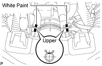
Connect the No. 1 and No. 2 ventilation hoses to the intake air connector pipe.
Tech Tips
-
Position the claws of the clamps as shown in the illustration.
-
Install the clamps so that they are within the hose's paint marks.
-
-
-
INSTALL NO. 1 AIR CLEANER INLET
-
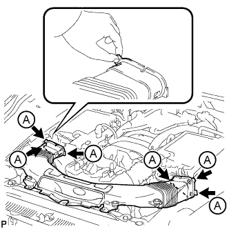
Align the holes with the connection areas labeled A, and attach the No. 1 air cleaner inlet.
-
Install the No. 1 air cleaner inlet with the 2 bolts.
- Torque:
- 5.0 N*m { 51 kgf*cm, 44 in.*lbf }
-
-
INSTALL ENGINE ROOM SIDE COVER RH
-
Install the engine room side cover RH with the 5 clips.
-
-
INSTALL ENGINE ROOM SIDE COVER LH
-
Install the engine room side cover LH with the 5 clips.
-
-
INSTALL AIR CLEANER INLET COVER SUB-ASSEMBLY
-
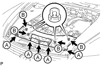
Attach the 4 clips labeled B.
Note
-
Make sure the clips are attached securely.
-
Attaching the clips forcefully or hitting the top of the clips may damage them.
-
-
Install the air cleaner inlet cover sub-assembly with the 5 clips labeled A.
-
-
INSTALL V-BANK COVER SUB-ASSEMBLY
-
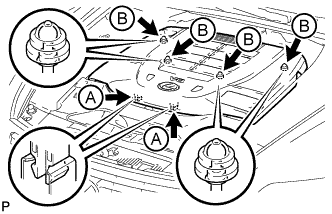
Slide the cover from the vehicle front toward the rear of the vehicle to attach the 2 clips labeled A, and then attach the 4 clips labeled B to install the V bank cover sub-assembly.
Note
-
Make sure the clips are attached securely.
-
Attaching the clips forcefully or hitting the top of the clips may damage them.
-
When attaching the clips labeled A, be sure to slide the cover from the front of the vehicle toward the rear of the vehicle.
-
-
-
CONNECT CABLE TO NEGATIVE BATTERY TERMINAL
Note
When disconnecting the cable, some systems need to be initialized after the cable is reconnected Click here.
-
INSTALL COWL TOP VENTILATOR LOUVER
-

for LHD:
Install the 6 clips and cowl top ventilator louver RH.
Note
If the cowl top ventilator louver RH is not properly installed, water may leak into the engine room and cause malfunctions. Therefore, make sure the cowl top ventilator louver RH is installed properly.
-

for RHD:
Install the 6 clips and cowl top ventilator louver LH.
Note
If the cowl top ventilator louver LH is not properly installed, water may leak into the engine room and cause malfunctions. Therefore, make sure the cowl top ventilator louver LH is installed properly.
-