OIL PUMP (for AWD) INSTALLATION

-
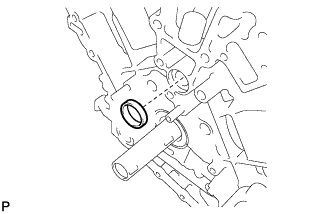
INSTALL WATER INLET PIPE
-
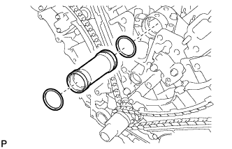
Apply soapy water to 2 new O-rings and install them to the inlet pipe.
-
Install the inlet pipe to the No. 1 heat exchanger cover.
-
-
INSTALL TIMING CHAIN COVER SUB-ASSEMBLY
-
Install a new oil pump gasket.
-
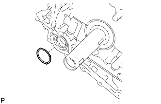
Install a new O-ring.
-
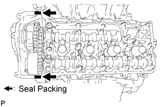
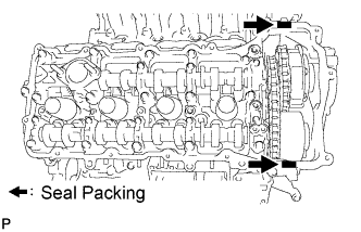
Apply seal packing in a continuous line to the timing chain cover as shown in the following illustration.
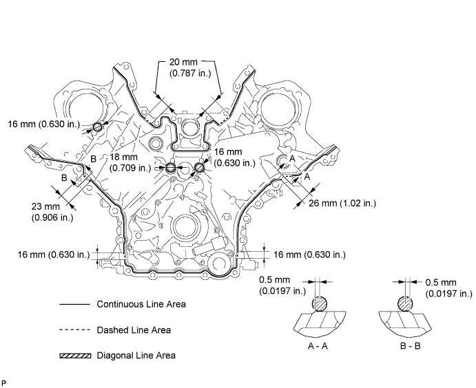
Seal packing Toyota Genuine Seal Packing Black, Three Bond 1207B or equivalent
-
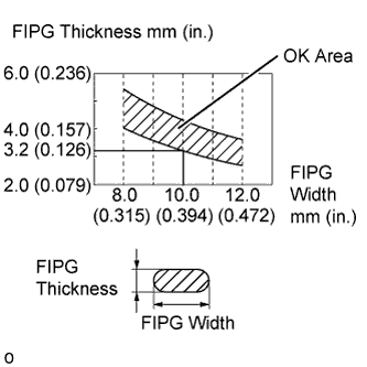
Apply Seal Packing as Follows Area Seal packing diameter Application position from inside edge of cover Continuous Line Area 3.0 to 4.0 mm (0.118 to 0.157 in.) 2.5 mm (0.0984 in.) Dashed Line Area 6.4 mm (0.252 in.) or more, or within OK area shown in illustration 0.5 mm (0.0197 in.) Diagonal Line Area 3.0 to 4.0 mm (0.118 to 0.157 in.) 5.5 mm (0.217 in.)
Note
-
When the contact surfaces are wet, wipe them with an oil-free cloth before applying seal packing.
-
Install the chain cover within 3 minutes and tighten the bolts within 10 minutes after applying seal packing.
-
Do not start the engine for at least 2 hours after installation.
-
-
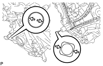
Align the drive rotor spline of the oil pump and the crankshaft as shown in the illustration. Install the spline and chain cover to the crankshaft.
-
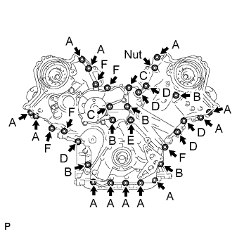
Temporarily install the 30 bolts and nut.
Bolt Length Item Length Thread diameter Bolt A 25 mm (0.984 in.) 8 mm (0.315 in.) Bolt B 55 mm (2.17 in.) 8 mm (0.315 in.) Bolt C 70 mm (2.76 in.) 8 mm (0.315 in.) Bolt D 35 mm (1.38 in.) 10 mm (0.394 in.) Bolt E 55 mm (2.17 in.) 10 mm (0.394 in.) Bolt F 80 mm (3.15 in.) 10 mm (0.394 in.) Note
Make sure that there is no oil on the bolt threads.
-
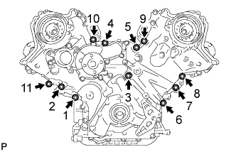
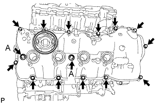
Tighten the 11 bolts in several steps, in the sequence shown in the illustration.
- Torque:
- 47 N*m { 479 kgf*cm, 35 ft.*lbf }
-
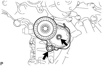
Temporarily install the belt tensioner with the standard bolt and 6 mm hexagon wrench bolt.
-
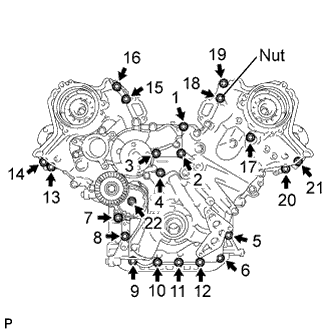
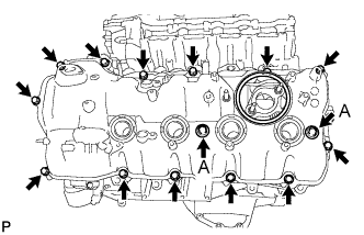
Tighten the 21 bolts and nut in several steps, in the sequence shown in the illustration.
- Torque:
- 23 N*m { 235 kgf*cm, 17 ft.*lbf }
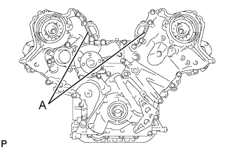
Note
After the installation, if the seal packing has seeped out at the areas labeled A shown in the illustration, wipe it off.
-
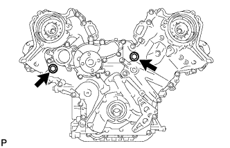
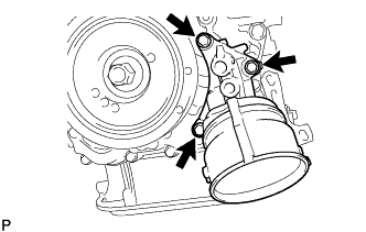
Install 2 new gaskets and the 2 plugs.
- Torque:
- 46 N*m { 469 kgf*cm, 34 ft.*lbf }
-
-
INSTALL CYLINDER HEAD COVER SUB-ASSEMBLY LH
-
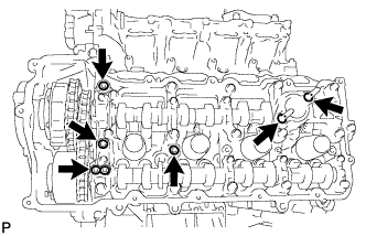
Install 4 new gaskets and 2 new O-rings to the camshaft bearing caps (No. 2, No. 3, No. 7).
-
Install a new gasket to the cylinder head cover.
Note
Remove any oil from the contact surface.
-
Apply seal packing as shown in the illustration.
Seal packing Toyota Genuine Seal Packing Black, Three Bond 1207B or equivalent Note
-
Remove any oil from the contact surface.
-
Install the cylinder head cover within 3 minutes and tighten the bolts within 15 minutes after applying seal packing.
-
Do not start the engine for at least 2 hours after the installation.
-
-
Install the cylinder head cover with 2 new seal washers and the 15 bolts.
- Torque:
- for bolt A
- 21 N*m { 214 kgf*cm, 15 ft.*lbf }
- except bolt A
- 12 N*m { 122 kgf*cm, 9 ft.*lbf }
-
-
INSTALL CYLINDER HEAD COVER SUB-ASSEMBLY RH
-
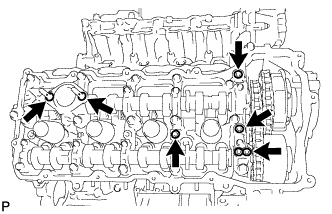
Install 4 new gaskets and 2 new O-rings to the camshaft bearing caps (No. 1, No. 3, No. 6).
-
Install a new gasket to the cylinder head cover.
Note
Remove any oil from the contact surface.
-
Apply seal packing as shown in the illustration.
Seal packing Toyota Genuine Seal Packing Black, Three Bond 1207B or equivalent Note
-
Remove any oil from the contact surface.
-
Install the cylinder head cover within 3 minutes and tighten the bolts within 15 minutes after applying seal packing.
-
Do not start the engine for at least 2 hours after the installation.
-
-
Install the cylinder head cover with 2 new seal washers and the 15 bolts.
- Torque:
- for bolt A
- 21 N*m { 214 kgf*cm, 15 ft.*lbf }
- except bolt A
- 12 N*m { 122 kgf*cm, 9 ft.*lbf }
-
-
INSTALL IGNITION COIL ASSEMBLY
-
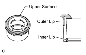
Perform a visual inspection of the spark plug tube gasket.
Standard Area Specified condition Upper surface No scratches or deformation Outer lip No scratches or deformation Inner lip No scratches If the result is not as specified, replace the spark plug tube gasket.
-
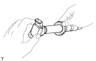
Slide the spark plug tube gasket onto the ignition coil assembly as shown in the illustration.
-
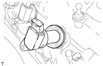
After installing the spark plug tube gasket, firmly insert the ignition coil assembly as shown in the illustration.
-
Install the 8 bolts.
- Torque:
- 10 N*m { 102 kgf*cm, 7 ft.*lbf }
-
Connect the 8 ignition coil assembly connectors.
-
-
INSTALL TIMING CHAIN CASE OIL SEAL
-
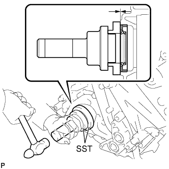
Using SST, tap in a new timing chain case oil seal until its surface is flush with the timing chain case edge.
- SST
- 09223-22010
- 09506-35010
Note
-
Keep the lip free from foreign matter.
-
Do not tap timing chain case oil seal at an angle.
-
-
INSTALL CRANKSHAFT TIMING GEAR KEY
-
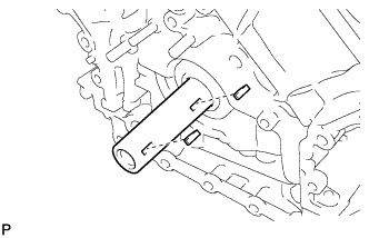
Install the 2 timing gear keys.
-
-
INSTALL CRANKSHAFT PULLEY
-
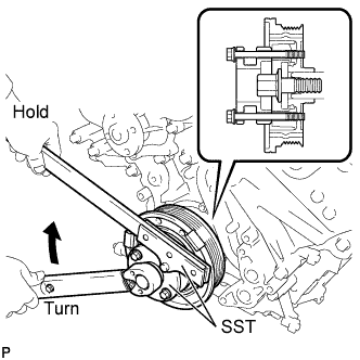
Align the pulley set key with the key groove of the pulley, and slide on the pulley.
-
Using SST, install the pulley bolt.
- SST
- 09213-54015 ( 90119-08216 )
- 09330-00021
- Torque:
- 300 N*m { 3059 kgf*cm, 221 ft.*lbf }
-
-
INSTALL OIL FILTER BRACKET
-
Install 2 new gaskets and the filter bracket with the 3 bolts.
- Torque:
- 21 N*m { 214 kgf*cm, 15 ft.*lbf }
-
-
INSTALL OIL FILTER ELEMENT
-
Clean the inside of the oil filter cap, the threads and O-ring groove.
-
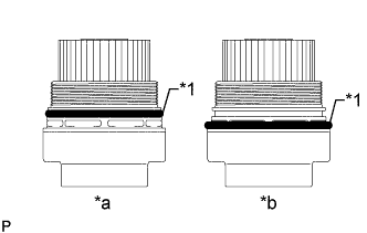
Text in Illustration *1 O-Ring *a CORRECT *b INCORRECT Apply a small amount of engine oil to a new O-ring for the cap, and then install O-ring to the groove of the oil filter cap.
-
Set a new oil filter element to the oil filter cap.
-
Remove any dirt or foreign matter from the installation surface of the engine.
-
Apply a small amount of engine oil to the O-ring again and install the oil filter cap.
-
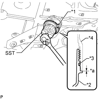
Text in Illustration *1 Oil Filter Bracket Clip *2 Oil Filter Cap *3 O-Ring *4 Oil Filter Bracket *a No Clearance Using SST, tighten the oil filter cap.
- SST
- 09228-06501
- Torque:
- 25 N*m { 255 kgf*cm, 18 ft.*lbf }
Note
-
Do not remove the oil filter bracket clip.
-
Make sure that the oil filter is installed securely as shown in the illustration.
-
Be careful that the O-ring does not get caught between the parts.
-
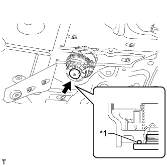
Text in Illustration *1 O-Ring Apply a small amount of engine oil to a new drain plug O-ring, and install it to the oil filter cap.
Note
Before installing the O-ring, remove any dirt or foreign matter from the installation surface of the oil filter cap.
-
Install the oil filter drain plug.
- Torque:
- 13 N*m { 133 kgf*cm, 10 ft.*lbf }
Note
Be careful that the O-ring does not get caught between the parts.
-
-
INSTALL CAMSHAFT TIMING CONTROL WITH EDU MOTOR ASSEMBLY LH
-
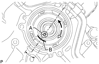
Turn the camshaft timing gear's eccentric shaft keyway part counterclockwise by hand and set it to the maximum retard angle.
Tech Tips
-
When the cam of the camshaft lifts the valve, the eccentric shaft becomes difficult to turn.
-
The position where the eccentric shaft stops is the maximum retard angle.
Note
When turning the eccentric shaft keyway part, do not use any tools as the keyway part may be damaged.
-
-
Turn the eccentric shaft clockwise until the groove labeled A and mark labeled B are aligned as shown in the illustration.
Tech Tips
Make sure that the groove labeled A is positioned as close as possible to the center of the mark labeled B.
-
Install a new O-ring to the timing chain cover.
-
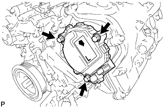
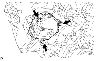
Align the joint of the camshaft timing control with EDU motor assembly LH and the keyway of the camshaft timing gear assembly, and install the camshaft timing control with EDU motor assembly LH with the 3 bolts.
- Torque:
- 21 N*m { 214 kgf*cm, 15 ft.*lbf }
Note
-
Do not allow foreign matter to contact the oil seal face of the camshaft timing control with EDU motor assembly LH (connecting surface with timing chain cover).
-
When installing the camshaft timing control with EDU motor assembly LH, do not use excessive force.
-
Do not drop the camshaft timing control with EDU motor assembly LH. If dropped, replace it.
-
Do not disassemble the camshaft timing control with EDU motor assembly LH. If disassembled, replace it.
Tech Tips
-
Check that [L] is printed on the label of the camshaft timing control with EDU motor assembly LH.
-
When installing the camshaft timing control with EDU motor assembly LH, be sure to align the timing chain cover knock pin with the camshaft timing control with EDU motor assembly LH pin hole.
-
Install the camshaft timing control with EDU motor assembly LH with the arrow facing upward.
-
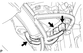
Connect the 2 camshaft timing control with EDU motor assembly LH connectors and engine wire clamp.
-
-
INSTALL CAMSHAFT TIMING CONTROL WITH EDU MOTOR ASSEMBLY RH
-
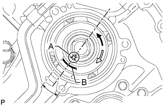
Turn the camshaft timing gear's eccentric shaft keyway part counterclockwise by hand and set it to the maximum retard angle.
Tech Tips
-
When the cam of the camshaft lifts the valve, the eccentric shaft becomes difficult to turn.
-
The position where the eccentric shaft stops is the maximum retard angle.
Note
When turning the eccentric shaft keyway part, do not use any tools as the keyway part may be damaged.
-
-
Turn the eccentric shaft clockwise until the groove labeled A and mark labeled B are aligned as shown in the illustration.
Tech Tips
Make sure that the groove labeled A is positioned as close as possible to the center of the mark labeled B.
-
Install a new O-ring to the timing chain cover.
-
Align the joint of the camshaft timing control with EDU motor assembly RH and the keyway of the camshaft timing gear assembly, and install the camshaft timing control with EDU motor assembly RH with the 3 bolts.
- Torque:
- 21 N*m { 214 kgf*cm, 15 ft.*lbf }
Note
-
Do not allow foreign matter to contact the oil seal face of the camshaft timing control with EDU motor assembly RH (connecting surface with timing chain cover).
-
When installing the camshaft timing control with EDU motor assembly RH, do not use excessive force.
-
Do not drop the camshaft timing control with EDU motor assembly RH. If dropped, replace it.
-
Do not disassemble the camshaft timing control with EDU motor assembly RH. If disassembled, replace it.
Tech Tips
-
Check that [R] is printed on the label of the camshaft timing control with EDU motor assembly RH.
-
When installing the camshaft timing control with EDU motor assembly RH, be sure to align the timing chain cover knock pin with the camshaft timing control with EDU motor assembly RH pin hole.
-
Install the camshaft timing control with EDU motor assembly RH with the arrow facing upward.
-
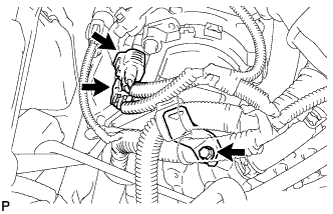
Install the engine wire bracket with the bolt.
- Torque:
- 12 N*m { 122 kgf*cm, 9 ft.*lbf }
-
Connect the 2 camshaft timing control with EDU motor assembly RH connectors.
-
-
INSTALL FRONT WATER BY-PASS JOINT
-
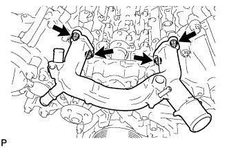
Install the 2 new gaskets and water by-pass joint with the 4 nuts.
- Torque:
- 21 N*m { 214 kgf*cm, 15 ft.*lbf }
-
-
INSTALL ENGINE AND TRANSMISSION