OIL PUMP (for 2WD) INSTALLATION

-
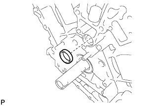
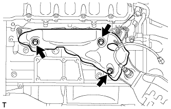
INSTALL WATER INLET PIPE
-
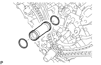
Apply soapy water to 2 new O-rings and install them to the inlet pipe.
-
Install the inlet pipe to the No. 1 heat exchanger cover.
-
-
INSTALL TIMING CHAIN COVER SUB-ASSEMBLY
-
Install a new oil pump gasket.
-
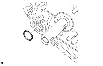
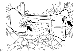
Install a new O-ring.
-
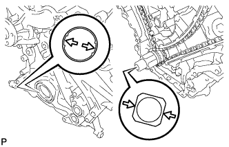
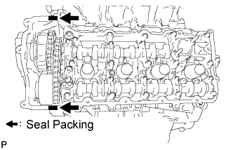
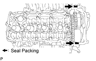
Apply seal packing in a continuous line to the timing chain cover as shown in the following illustration.
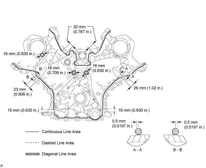
Seal packing Toyota Genuine Seal Packing Black, Three Bond 1207B or equivalent
-
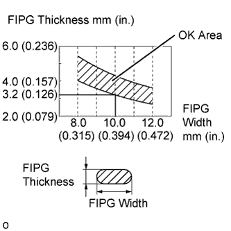
Apply Seal Packing as Follows Area Seal packing diameter Application position from inside edge of cover Continuous Line Area 3.0 to 4.0 mm (0.1181 to 0.1575 in.) 2.5 mm (0.098 in.) Dashed Line Area 6.4 mm (0.2520 in.) or more, or within OK area shown in illustration 0.5 mm (0.020 in.) Diagonal Line Area 3.0 to 4.0 mm (0.1181 to 0.1575 in.) 5.5 mm (0.217 in.)
Note
-
When the contact surfaces are wet, wipe them with an oil-free cloth before applying seal packing.
-
Install the chain cover within 3 minutes and tighten the bolts within 10 minutes after applying seal packing.
-
Do not start the engine for at least 2 hours after installation.
-
-
Align the drive rotor spline of the oil pump and the crankshaft as shown in the illustration. Install the spline and chain cover to the crankshaft.
-
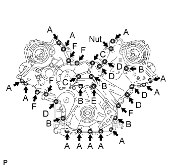
Temporarily install the 30 bolts and nut.
Bolt Length Item Length Thread diameter Bolt A 25 mm (0.984 in.) 8 mm (0.315 in.) Bolt B 55 mm (2.165 in.) 8 mm (0.315 in.) Bolt C 70 mm (2.756 in.) 8 mm (0.315 in.) Bolt D 35 mm (1.378 in.) 10 mm (0.394 in.) Bolt E 55 mm (2.165 in.) 10 mm (0.394 in.) Bolt F 80 mm (3.150 in.) 10 mm (0.394 in.) Note
Make sure that there is no oil on the bolt threads.
-
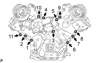
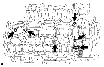
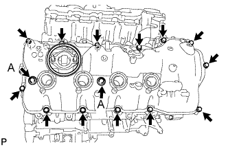
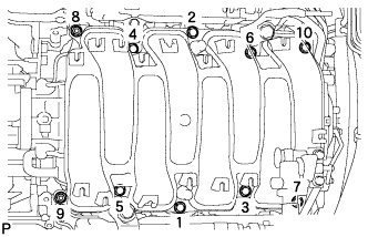
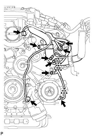
Tighten the 11 bolts in several steps, in the sequence shown in the illustration.
- Torque:
- 47 N*m { 479 kgf*cm, 35 ft.*lbf }
-
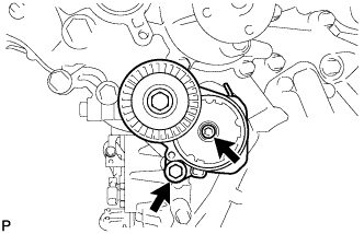
Temporarily tighten the belt tensioner with the standard bolt and 6 mm hexagon wrench bolt.
-
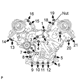
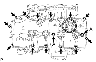
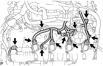
Tighten the 21 bolts and nut in several steps, in the sequence shown in the illustration.
- Torque:
- 23 N*m { 235 kgf*cm, 17 ft.*lbf }
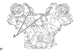
Note
After the installation, if the seal packing has seeped out at the areas labeled A shown in the illustration, wipe it off.
-
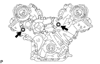
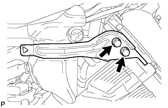
Install the 2 new gaskets and the 2 plugs.
- Torque:
- 46 N*m { 469 kgf*cm, 34 ft.*lbf }
-
-
INSTALL CYLINDER HEAD COVER SUB-ASSEMBLY LH
-
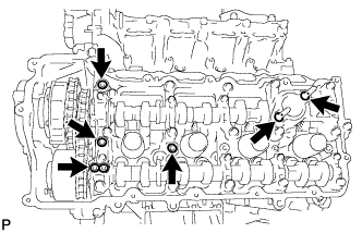
Install 4 new gaskets and 2 new O-rings to the camshaft bearing caps (No. 2, No. 3, No. 7).
-
Install a new gasket to the cylinder head cover.
Note
Remove any oil from the contact surface.
-
Apply seal packing as shown in the illustration.
Seal packing Toyota Genuine Seal Packing Black, Three Bond 1207B or equivalent Note
-
Remove any oil from the contact surface.
-
Install the cylinder head cover within 3 minutes and tighten the bolts within 15 minutes after applying seal packing.
-
Do not start the engine for at least 2 hours after the installation.
-
-
Install the cylinder head cover with 2 new seal washers and the 15 bolts.
- Torque:
- for bolt A
- 21 N*m { 214 kgf*cm, 15 ft.*lbf }
- except bolt A
- 12 N*m { 122 kgf*cm, 9 ft.*lbf }
-
-
INSTALL CYLINDER HEAD COVER SUB-ASSEMBLY RH
-
Install 4 new gaskets and 2 new O-rings to the camshaft bearing caps (No. 1, No. 3, No. 6).
-
Install a new gasket to the cylinder head cover.
Note
Remove any oil from the contact surface.
-
Apply seal packing as shown in the illustration.
Seal packing Toyota Genuine Seal Packing Black, Three Bond 1207B or equivalent Note
-
Remove any oil from the contact surface.
-
Install the cylinder head cover within 3 minutes and tighten the bolts within 15 minutes after applying seal packing.
-
Do not start the engine for at least 2 hours after the installation.
-
-
Install the cylinder head cover with 2 new seal washers and the 15 bolts.
- Torque:
- for bolt A
- 21 N*m { 214 kgf*cm, 15 ft.*lbf }
- except bolt A
- 12 N*m { 122 kgf*cm, 9 ft.*lbf }
-
-
INSTALL IGNITION COIL ASSEMBLY
-
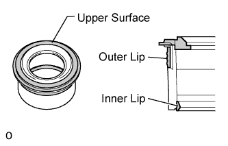
Perform a visual inspection of the spark plug tube gasket.
Standard Area Specified condition Upper surface No scratches or deformation Outer lip No scratches or deformation Inner lip No scratches If the result is not as specified, replace the spark plug tube gasket.
-
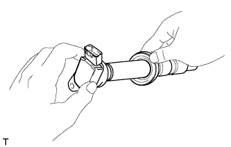
Slide the spark plug tube gasket onto the ignition coil assembly as shown in the illustration.
-
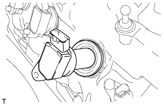
After installing the spark plug tube gasket, firmly insert the ignition coil assembly as shown in the illustration.
-
Install the 8 bolts.
- Torque:
- 10 N*m { 102 kgf*cm, 7 ft.*lbf }
-
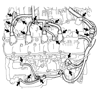
Connect the 8 ignition coil assembly connectors.
-
-
INSTALL CRANKSHAFT PULLEY
-
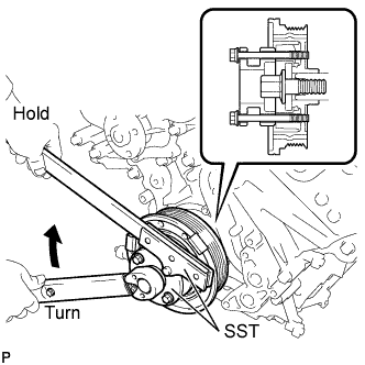
Align the pulley set key with the key groove of the pulley, and slide on the pulley.
-
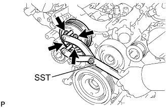
Using SST, install the pulley bolt.
- SST
- 09213-54015 ( 90119-08216 )
- 09330-00021
- Torque:
- 300 N*m { 3059 kgf*cm, 221 ft.*lbf }
-
-
INSTALL RESONATOR BRACKET SUB-ASSEMBLY
-
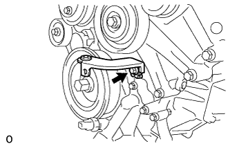
Install the resonator bracket sub-assembly with the bolt.
- Torque:
- 20 N*m { 204 kgf*cm, 15 ft.*lbf }
-
-
INSTALL OIL FILTER BRACKET
-
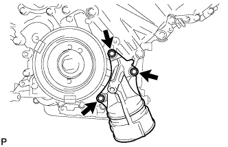
Install 2 new gaskets and the filter bracket with the 3 bolts.
- Torque:
- 21 N*m { 214 kgf*cm, 15 ft.*lbf }
-
-
INSTALL OIL FILTER ELEMENT
-
Clean the inside of the oil filter cap, the threads and O-ring groove.
-
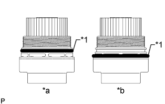
Text in Illustration *1 O-Ring *a CORRECT *b INCORRECT Apply a small amount of engine oil to a new O-ring for the cap, and then install the O-ring to the groove of the oil filter cap.
Note
-
Be sure to install the O-ring in the proper location, otherwise oil may leak.
-
Do not twist the O-ring.
-
-
Set a new oil filter element to the oil filter cap.
-
Remove any dirt or foreign matter from the installation surface of the engine.
-
Apply a small amount of engine oil to the O-ring again and install the oil filter cap.
Note
Do not pinch the O-ring for the cap.
-
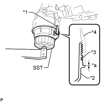
Text in Illustration *1 Oil Filter Bracket Clip *2 Oil Filter Cap *3 O-Ring *4 Oil Filter Bracket *a No Clearance Using SST, tighten the oil filter cap.
- SST
- 09228-06501
- Torque:
- 25 N*m { 255 kgf*cm, 18 ft.*lbf }
Note
-
Do not remove the oil filter bracket clip.
-
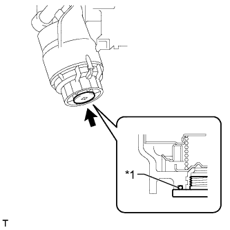
Make sure that the oil filter is installed securely as shown in the illustration.
-
Be careful that the O-ring does not get caught between the parts.
-
Text in Illustration *1 O-Ring Apply a small amount of engine oil to a new drain plug O-ring, and install it to the oil filter cap.
Note
Before installing the O-ring, remove any dirt or foreign matter from the installation surface of the oil filter cap.
-
Install the oil filter drain plug.
- Torque:
- 13 N*m { 133 kgf*cm, 10 ft.*lbf }
Note
Be careful that the O-ring does not get caught between the parts.
-
-
INSTALL CAMSHAFT TIMING CONTROL WITH EDU MOTOR ASSEMBLY LH
-
Turn the camshaft timing gear's eccentric shaft keyway part counterclockwise by hand and set it to the maximum retard angle.
Tech Tips
-
When the cam of the camshaft lifts the valve, the eccentric shaft becomes difficult to turn.
-
The position where the eccentric shaft stops is the maximum retard angle.
Note
When turning the eccentric shaft keyway part, do not use any tools as the keyway part may be damaged.
-
-
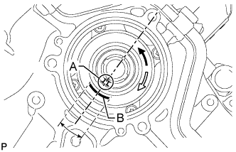
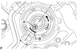
Turn the eccentric shaft clockwise until the groove labeled A and mark labeled B are aligned as shown in the illustration.
Tech Tips
Make sure that the groove labeled A is positioned as close as possible to the center of the mark labeled B.
-
Install a new O-ring to the timing chain cover.
-
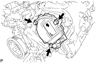
Align the joint of the camshaft timing control with EDU motor assembly LH and the keyway of the camshaft timing gear assembly, and install the camshaft timing control with EDU motor assembly LH with the 3 bolts.
- Torque:
- 21 N*m { 214 kgf*cm, 15 ft.*lbf }
Note
-
Do not allow foreign matter to contact the oil seal face of the camshaft timing control with EDU motor assembly LH (connecting surface with timing chain cover).
-
When installing the camshaft timing control with EDU motor assembly LH, do not use excessive force.
-
Do not drop the camshaft timing control with EDU motor assembly LH. If dropped, replace it.
-
Do not disassemble the camshaft timing control with EDU motor assembly LH. If disassembled, replace it.
Tech Tips
-
Check that [L] is printed on the label of the camshaft timing control with EDU motor assembly LH.
-
When installing the camshaft timing control with EDU motor assembly LH, be sure to align the timing chain cover knock pin with the camshaft timing control with EDU motor assembly LH pin hole.
-
Install the camshaft timing control with EDU motor assembly LH with the arrow facing upward.
-
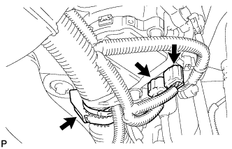
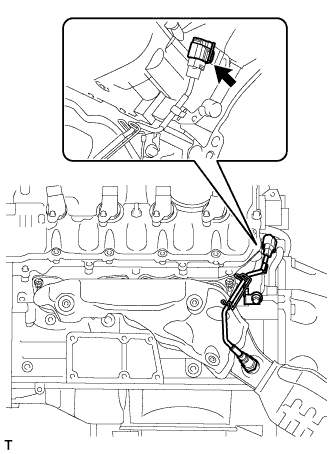
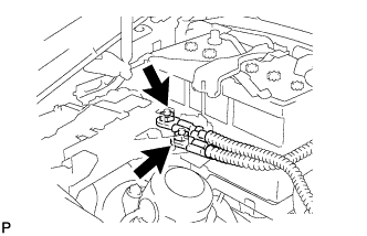
Connect the 2 camshaft timing control with EDU motor assembly LH connectors and engine wire clamp.
-
-
INSTALL CAMSHAFT TIMING CONTROL WITH EDU MOTOR ASSEMBLY RH
-
Turn the camshaft timing gear's eccentric shaft keyway part counterclockwise by hand and set it to the maximum retard angle.
Tech Tips
-
When the cam of the camshaft lifts the valve, the eccentric shaft becomes difficult to turn.
-
The position where the eccentric shaft stops is the maximum retard angle.
Note
When turning the eccentric shaft keyway part, do not use any tools as the keyway part may be damaged.
-
-
Turn the eccentric shaft clockwise until the groove labeled A and mark labeled B are aligned as shown in the illustration.
Tech Tips
Make sure that the groove labeled A is positioned as close as possible to the center of the mark labeled B.
-
Install a new O-ring to the timing chain cover.
-
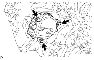
Align the joint of the camshaft timing control with EDU motor assembly RH and the keyway of the camshaft timing gear assembly, and install the camshaft timing control with EDU motor assembly RH with the 3 bolts.
- Torque:
- 21 N*m { 214 kgf*cm, 15 ft.*lbf }
Note
-
Do not allow foreign matter to contact the oil seal face of the camshaft timing control with EDU motor assembly RH (connecting surface with timing chain cover).
-
When installing the camshaft timing control with EDU motor assembly RH, do not use excessive force.
-
Do not drop the camshaft timing control with EDU motor assembly RH. If dropped, replace it.
-
Do not disassemble the camshaft timing control with EDU motor assembly RH. If disassembled, replace it.
Tech Tips
-
Check that [R] is printed on the label of the camshaft timing control with EDU motor assembly RH.
-
When installing the camshaft timing control with EDU motor assembly RH, be sure to align the timing chain cover knock pin with the camshaft timing control with EDU motor assembly RH pin hole.
-
Install the camshaft timing control with EDU motor assembly RH with the arrow facing upward.
-
Install the engine wire bracket with the bolt.
- Torque:
- 12 N*m { 122 kgf*cm, 9 ft.*lbf }
-
Connect the 2 camshaft timing control with EDU motor assembly RH connectors.
-
-
INSTALL FRONT WATER BY-PASS JOINT
-
Install the 2 new gaskets and water by-pass joint with the 4 nuts.
- Torque:
- 21 N*m { 214 kgf*cm, 15 ft.*lbf }
-
-
INSTALL NO. 1 IDLER PULLEY SUB-ASSEMBLY
-
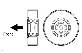
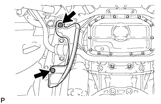
Install the No. 1 idler pulley sub-assembly with the bolt.
- Torque:
- 43 N*m { 438 kgf*cm, 32 ft.*lbf }
Tech Tips
Install the No. 1 idler pulley sub-assembly in the direction shown in the illustration.
-
-
INSTALL NO. 2 IDLER PULLEY SUB-ASSEMBLY
-
Install the No. 2 idler pulley sub-assembly with the bolt.
- Torque:
- 43 N*m { 438 kgf*cm, 32 ft.*lbf }
-
-
INSTALL WATER PUMP PULLEY
-
Temporarily install the pulley with the 4 bolts.
-
Using SST, hold the pulley and tighten the 4 bolts.
- SST
- 09960-10010 ( 09962-01000, 09963-01000 )
- Torque:
- 21 N*m { 214 kgf*cm, 15 ft.*lbf }
-
-
INSTALL WATER INLET HOUSING
-
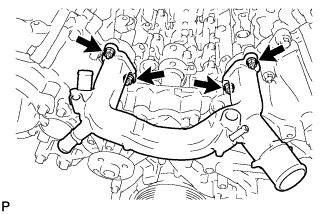
Install the inlet housing and new gasket with the 3 bolts.
- Torque:
- 21 N*m { 214 kgf*cm, 15 ft.*lbf }
-
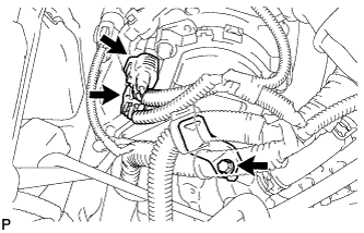
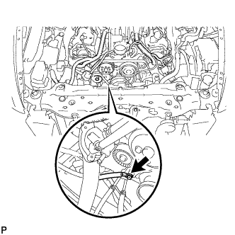
Using needle-nose pliers, grip the claws of the clips and slide the clips to connect the water by-pass hoses and water inlet hose.
-
-
INSTALL FUEL PUMP ASSEMBLY (for High Pressure)
-
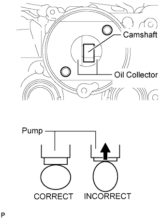
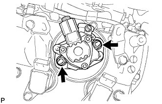
Turn the camshaft until the flat of the cam is facing the cylinder head cover's fuel pump attachment hole, as shown in the illustration.
Tech Tips
By not using the camshaft lobe to push up the pump lifter surface, it is easier to install the fuel pump and No. 3 fuel pipe later.
-
Pour 30 cm3(1.8 cu. in.) of engine oil through the cylinder head cover's fuel pump attachment hole into the cylinder head oil collector.
-
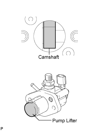
Apply a coat of engine oil to the pump activation cam and pump lifter.
-
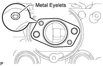
Install a new fuel pump insulator to the cylinder head cover. Then pass the 2 stud bolts through the holes of the fuel pump and set them on the insulator.
Note
Install the insulator so that the open sides of the metal eyelets are facing outward, as shown in the illustration.
-
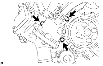
Temporarily install the fuel pump with the 2 nuts.
-
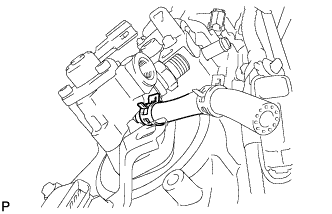
Connect the fuel hose.
-
-
INSTALL NO. 3 FUEL PIPE SUB-ASSEMBLY
-
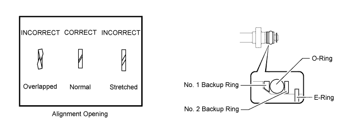
Install a new O-ring, new backup rings (No. 1 and No. 2) and new E-ring to the fuel injector as shown in the illustration.
Note
-
Check that there is no foreign matter or damaged areas in the injector's O-ring groove.
-
Check that the No. 1 and No. 2 backup rings are installed in the correct direction.
-
Make sure that the backup rings and O-ring are installed in the correct order.
-
Check that the alignment openings of the backup rings are not overlapped or stretched as shown in the illustration.
-
After installing the O-ring, check that it is not contaminated with foreign matter and is not damaged.
-
-
Apply engine oil to the O-ring.
Note
Make sure there is no gasoline on the O-ring and inside the installation hole.
-
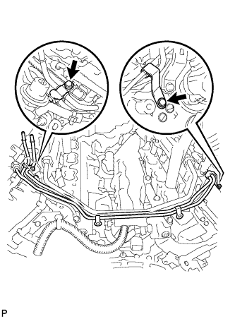
Temporarily install the No. 3 fuel pipe to the delivery pipe with the 2 bolts.
-
Temporarily install the No. 3 fuel pipe sub-assembly to the fuel pump.
Note
Be careful not to damage the sealing surface of the fuel pipe when temporarily installing the fuel pipe.
-
Tighten the 2 bolts in several passes.
- Torque:
- 10 N*m { 102 kgf*cm, 7 ft.*lbf }
-
Tighten the 2 nuts in several passes.
- Torque:
- 25 N*m { 255 kgf*cm, 18 ft.*lbf }
-
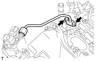
Using a 19 mm union nut wrench, tighten the union nut.
- Torque:
- 30 N*m { 306 kgf*cm, 22 ft.*lbf }
Note
-
There must be absolutely no free play in the union on the fuel pump side. If the union on the fuel pump side has free play, replace the fuel pump.
-
Use the formula to calculate special torque values for situations where a union nut wrench is combined with a torque wrench Click here.
-
Connect the fuel pump connector.
-
-
INSTALL NO. 2 FUEL PIPE SUB-ASSEMBLY
Tech Tips
The installation procedures are the same as the No. 3 fuel pipe sub-assembly.
-
INSTALL FUEL PRESSURE PULSATION DAMPER ASSEMBLY
-
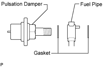
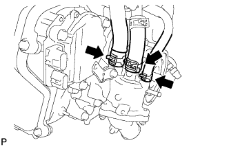
Apply a light coat of engine oil to the threads and gasket seating surfaces of the 2 fuel pressure pulsation damper assemblies.
-
Temporarily install each dampers together with 2 new gaskets and the pipe to the fuel pump.
-
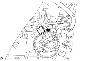
Install the 2 clamp bolts.
- Torque:
- 10 N*m { 102 kgf*cm, 7 ft.*lbf }
-
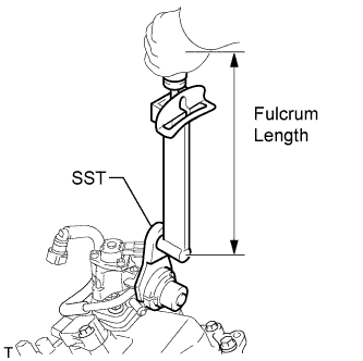
Using SST, tighten the 2 dampers.
- SST
- 09612-24014 ( 09617-24011 )
- Torque:
- without SST
- 36 N*m { 367 kgf*cm, 27 ft.*lbf }
- with SST
- 31 N*m { 313 kgf*cm, 23 ft.*lbf }
Note
There must be absolutely no free play in the union on the fuel pump side. If the union on the fuel pump side has free play, replace the fuel pump.
Tech Tips
-
Use a torque wrench with a fulcrum length of 300 mm (11.8 in.). When using a torque wrench with a fulcrum length that is not 300 mm (11.8 in.). calculate the torque specification for the torque wrench and SST based on the "without SST" torque specification Click here.
-
Make sure SST and the torque wrench are connected in a straight line.
-
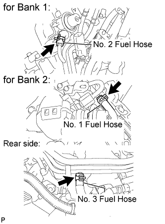
Connect the 3 fuel hoses.
-
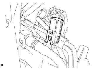
Connect the connector to the delivery pipe.
-
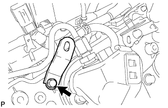
Install the bracket with the bolt.
- Torque:
- 10 N*m { 102 kgf*cm, 7 ft.*lbf }
-
-
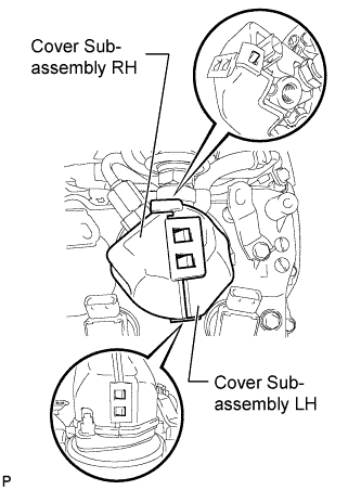
INSTALL ENGINE COVER SUB-ASSEMBLY
-
Attach the 5 claws and install the engine cover LH and RH to the fuel pump.
-
-
INSTALL NO. 3 ENGINE COVER
-
Install the No. 3 engine cover with the 2 clips.
-
Install the bracket with the 2 bolts.
- Torque:
- 10 N*m { 102 kgf*cm, 7 ft.*lbf }
-
-
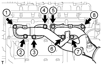
INSTALL INTAKE MANIFOLD
-
Install 2 new gasket to the intake manifold.
-
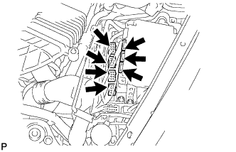
Temporarily install the intake manifold with the 2 nuts and 8 bolts. Then tighten the 2 nuts and 8 bolts uniformly in the order shown in the illustration.
- Torque:
- 21 N*m { 214 kgf*cm, 15 ft.*lbf }
-
Connect the No. 1 ventilation hose to the intake manifold.
Note
Make sure that the clip is facing as shown in the illustration.
-
-
INSTALL WATER BY-PASS PIPE SUB-ASSEMBLY
-
Install the water by-pass pipe sub-assembly to the intake manifold with the 2 bolts.
- Torque:
- 10 N*m { 102 kgf*cm, 7 ft.*lbf }
-
Connect the heater water inlet hose, heater water outlet hose, water inlet hose, and No. 3 water by-pass hose to the water by-pass pipe sub-assembly with the 4 clamps.
Note
Make sure that the No. 3 water by-pass hose clip is facing as shown in the illustration.
-
-
INSTALL NO. 1 ENGINE COVER
-
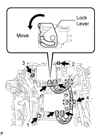
INSTALL INJECTOR DRIVER
-
Install the injector driver to the intake manifold by installing the 2 bolts and 2 nuts in the order shown in the illustration.
- Torque:
- 10 N*m { 102 kgf*cm, 7 ft.*lbf }
-
Connect the 4 wire harness connectors to the injector driver. Then move the lock lever as shown in the illustration to lock the connectors.
-
Connect the 2 clamps to the injector driver.
-
-
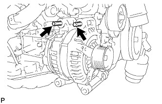
INSTALL GENERATOR ASSEMBLY
-
Using an E8 "TORX" socket wrench, set the generator with the 2 stud bolts.
- Torque:
- 10 N*m { 102 kgf*cm, 7 ft.*lbf }
-
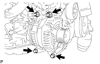
Install the generator with the 2 bolts and 2 nuts.
- Torque:
- 43 N*m { 438 kgf*cm, 32 ft.*lbf }
-
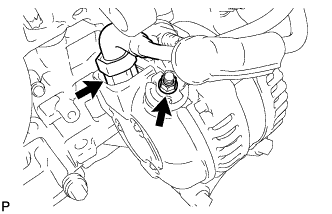
Connect the generator connector.
-
Connect the harness to the +B terminal with the nut.
- Torque:
- 12 N*m { 122 kgf*cm, 9 ft.*lbf }
-
-
INSTALL ENGINE OIL LEVEL DIPSTICK GUIDE
-
Apply a light coat of engine oil to a new O-ring.
-
Install the O-ring to the engine oil level dipstick guide.
-
Install the engine oil level dipstick guide with the 2 bolts.
- Torque:
- 10 N*m { 102 kgf*cm, 7 ft.*lbf }
-
Install the engine oil level dipstick.
-
-
CONNECT COOLER COMPRESSOR ASSEMBLY
-
Connect the cooler compressor assembly with the 2 stud bolts, 2 nuts and 2 bolts.
- Torque:
- for stud bolts
- 10 N*m { 102 kgf*cm, 7 ft.*lbf }
- for nuts
- 25 N*m { 255 kgf*cm, 18 ft.*lbf }
- for bolts
- 25 N*m { 255 kgf*cm, 18 ft.*lbf }
-
-
INSTALL EXHAUST MANIFOLD SUB-ASSEMBLY LH
-
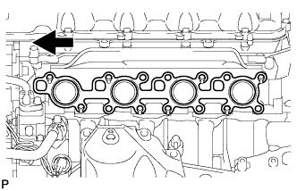
Install a new gasket.
Text in Illustration 
Front -
Install the exhaust manifold LH, and install 8 new nuts in the order shown in the illustration.
- Torque:
- 21 N*m { 214 kgf*cm, 15 ft.*lbf }
-
-
INSTALL NO. 2 EXHAUST MANIFOLD HEAT INSULATOR
-
Install the exhaust manifold heat insulator with the 3 bolts.
- Torque:
- 10 N*m { 102 kgf*cm, 7 ft.*lbf }
-
Connect the air fuel ratio sensor connector.
-
-
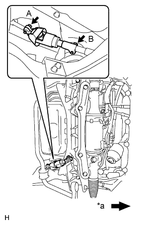
INSTALL NO. 2 STEERING INTERMEDIATE SHAFT ASSEMBLY
-
Install the clamp to the steering column hole shield.
-
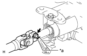
Text in Illustration *a Matchmark Align the matchmarks on the No. 2 steering intermediate shaft and steering column.
-
Install the bolt.
- Torque:
- 35 N*m { 360 kgf*cm, 26 ft.*lbf }
-
-
INSTALL STEERING SLIDING YOKE WITH SHAFT SUB-ASSEMBLY (for LHD with VGRS)
-
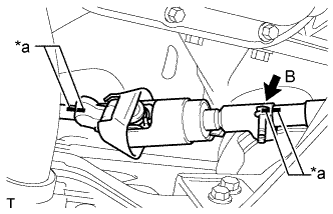
Text in Illustration *a Matchmark Align the matchmarks on the No. 2 steering intermediate shaft assembly and steering sliding with shaft yoke.
-
Align the matchmarks on the steering sliding with shaft yoke and power steering link.
-
Temporarily install bolt B.
Note
Do not tighten the bolt.
-
Text in Illustration *a Front of the vehicle Install bolt A and tighten bolt B.
- Torque:
- 35 N*m { 360 kgf*cm, 26 ft.*lbf }
-
-
INSTALL STEERING SLIDING YOKE WITH SHAFT SUB-ASSEMBLY (for LHD without VGRS)
-
Text in Illustration *a Matchmark Align the matchmarks on the No. 2 steering intermediate shaft and steering sliding with shaft yoke.
-
Align the matchmarks on the steering sliding with shaft yoke and steering intermediate shaft.
-
Temporarily install bolt B.
Note
Do not tighten the bolt.
-
Text in Illustration *a Front of the vehicle Install bolt A and tighten bolt B.
- Torque:
- 35 N*m { 360 kgf*cm, 26 ft.*lbf }
-
-
INSTALL FRONT SUSPENSION MEMBER REINFORCEMENT LH
-
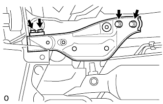
Install the front suspension member reinforcement LH to the vehicle with the 4 bolts.
- Torque:
- 50 N*m { 510 kgf*cm, 37 ft.*lbf }
-
-
INSTALL FRONT STABILIZER BAR
-
INSTALL FRONT EXHAUST PIPE ASSEMBLY
-
CONNECT ENGINE WIRE
-
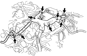
Connect the engine wire with the 4 nuts.
- Torque:
- 10 N*m { 102 kgf*cm, 7 ft.*lbf }
-
Connect the clamp and install the 2 clamp brackets with the 2 bolts.
- Torque:
- 10 N*m { 102 kgf*cm, 7 ft.*lbf }
-
Connect the intake air control valve actuator connector.
-
Connect the No. 1 vacuum switching valve connector.
-
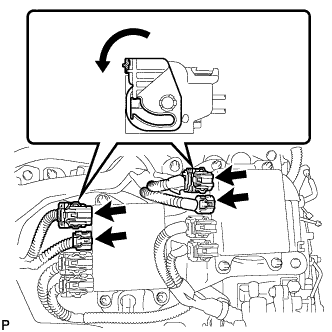
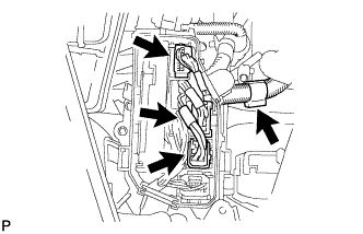
Connect the 4 injector driver connectors as shown in the illustration.
-
Connect the ground wire with the bolt.
- Torque:
- 21 N*m { 214 kgf*cm, 15 ft.*lbf }
-
for Engine Room RH Side:
-
Connect the 2 clamps and install the 3 clamp brackets with the 3 bolts.
- Torque:
- 10 N*m { 102 kgf*cm, 7 ft.*lbf }
-
Connect the engine oil level sensor connector.
-
Connect the crankshaft position sensor connector.
-
Connect the starter connector and starter wire with the nut.
- Torque:
- 10 N*m { 102 kgf*cm, 7 ft.*lbf }
-
Connect the generator connector and generator wire with the nut.
- Torque:
- 12 N*m { 122 kgf*cm, 9 ft.*lbf }
-
Connect the camshaft position sensor connector.
-
Connect the engine wire connector.
-
Connect the 2 camshaft timing control motor connectors (for Bank 2).
-
Connect the fuel pump connector (for high pressure).
-
Connect the 2 VVT sensor connectors.
-
Connect the 4 ignition coil connectors.
-
Connect the camshaft timing control valve connector.
-
Connect the wires to the No. 1 engine room junction block with the 2 nuts.
- Torque:
- 13 N*m { 133 kgf*cm, 10 ft.*lbf }
-
Connect the 3 connectors to the front controller with the clamp.
-
-
for Engine Room LH Side:
-
Install the clamp bracket with the bolt.
- Torque:
- 10 N*m { 102 kgf*cm, 7 ft.*lbf }
-
Connect the 3 clamps and 3 ground wires with the 3 bolts.
- Torque:
- 10 N*m { 102 kgf*cm, 7 ft.*lbf }
-
Attach the clamp and connect the cooler compressor connector.
-
Connect the 2 camshaft timing control motor connectors (for Bank 1).
-
Connect the engine oil pressure sensor connector.
-
Connect the engine coolant temperature sensor connector.
-
Connect the clamp and install the 2 clamp brackets with the 2 bolts.
- Torque:
- 10 N*m { 102 kgf*cm, 7 ft.*lbf }
-
Connect the No. 8 engine wire connector.
-
Connect the fuel pump connector (for high pressure).
-
Connect the 2 VVT sensor connectors.
-
Connect the 4 ignition coil connectors.
-
Connect the camshaft timing control valve connector.
-
Connect the 3 ECT connectors and 4 ECM connectors.
-
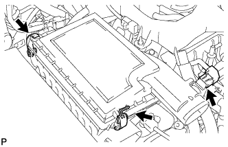
Install the ECM box cover (upper).
-
-
-
INSTALL ENGINE ROOM ECU OUTLET DUCT
-
Install the engine room ECU outlet duct.
-
-
INSTALL SKID CONTROL ECU BRACKET
-
for LHD: Click here
-
for RHD: Click here
-
-
INSTALL NO. 2 ENGINE COVER (for LHD)
-
Install the No. 2 engine cover with the 4 nuts.
- Torque:
- 21 N*m { 214 kgf*cm, 15 ft.*lbf }
-
-
CONNECT NO. 2 RADIATOR HOSE
-
CONNECT NO. 1 RADIATOR HOSE
-
INSTALL V-RIBBED BELT
-
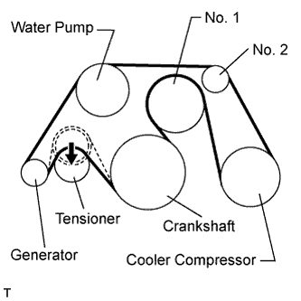
Install the V-ribbed belt as shown in the illustration.
Note
Check that the V-ribbed belt is properly set to each pulley.
-
Rotate the tensioner pulley counterclockwise, and then remove the fix bar.
-
-
-
INSTALL RADIATOR RESERVOIR ASSEMBLY
-
Install the radiator reservoir assembly with the 2 bolts.
- Torque:
- 5.0 N*m { 51 kgf*cm, 44 in.*lbf }
-
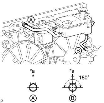
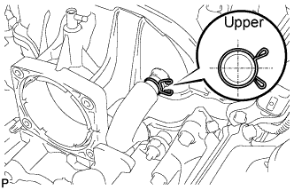
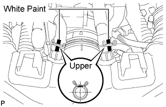
Text in Illustration *a Upper Connect the 2 reservoir hoses.
Tech Tips
The direction of the hose clamp is indicated in the illustration.
-
-
INSTALL AIR CLEANER ASSEMBLY LH
-
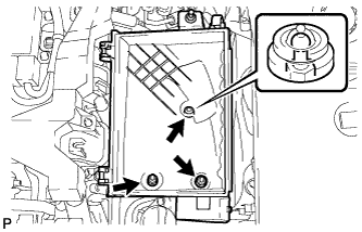
Install the air cleaner case LH with the 2 nuts and clip.
- Torque:
- 5.0 N*m { 51 kgf*cm, 44 in.*lbf }
-
Install the air cleaner filter element to the air cleaner case LH.
-
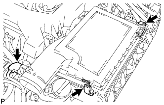
Install the air cleaner cap LH with the 2 clamps.
-
Connect the mass air flow meter connector.
-
-
INSTALL AIR CLEANER ASSEMBLY RH
-
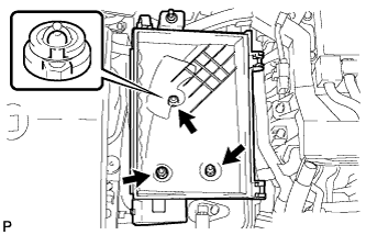
Install the air cleaner case RH with the 2 nuts and clip.
- Torque:
- 5.0 N*m { 51 kgf*cm, 44 in.*lbf }
-
Install the air cleaner filter element to the air cleaner case RH.
-
Install the air cleaner cap RH with the 2 clamps.
-
Connect the mass air flow meter connector.
-
-
INSTALL INTAKE AIR CONNECTOR PIPE
-
Install the intake air sound creator.
Tech Tips
Only perform this procedure when replacement of the intake air sound creator is necessary.
-
Install the intake air sound creator with the bolt and hose clamp.
- Torque:
- 2.0 N*m { 20 kgf*cm, 18 in.*lbf }
-
-
Align the protrusion of the intake air resonator with the cutout of the bracket and insert the protrusion.
-
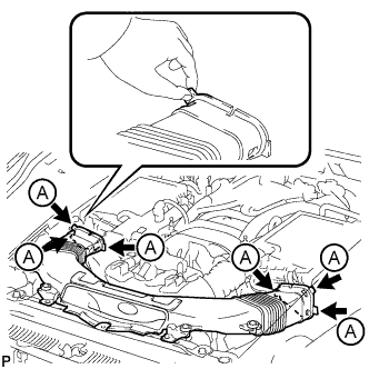
Install the intake air connector pipe with the 3 hose clamps.
- Torque:
- for intake air connector pipe and throttle body
- 4.8 N*m { 49 kgf*cm, 42 in.*lbf }
- for intake air connector pipe and air cleaner cap
- 3.8 N*m { 39 kgf*cm, 34 in.*lbf }
Tech Tips
-
Insert the protrusion of the intake air connector pipe into the hole of the hose clamp.
-
The intake air connector pipe and throttle body clamp can be tightened within the range of 4.0 N*m (41 kgf*cm, 35 in.*lbf) to 5.5 N*m (56 kgf*cm, 49 in.*lbf), and the intake air connector pipe and air cleaner cap clamp can be tightened within the range of 2.0 N*m (20 kgf*cm, 18 in.*lbf) to 5.5 N*m (56 kgf*cm, 49 in.*lbf).
-
Attach the 2 wire harness clamps.
-
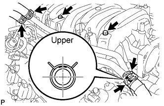
Connect the No. 1 and No. 2 ventilation hoses to the intake air connector pipe.
Tech Tips
-
Position the claws of the clamps as shown in the illustration.
-
Install the clamps so that they are within the hose's paint marks.
-
-
-
INSTALL NO. 1 AIR CLEANER INLET
-
Align the holes with the connection areas labeled A, and attach the No. 1 air cleaner inlet.
-
Install the No. 1 air cleaner inlet with the 2 bolts.
- Torque:
- 5.0 N*m { 51 kgf*cm, 44 in.*lbf }
-
-
INSTALL ENGINE UNDER COVER REAR LH
-
Install the engine under cover rear LH with the 2 screws.
-
-
INSTALL ENGINE UNDER COVER REAR RH
Tech Tips
Install the RH side following the same procedures as the LH side.
-
INSTALL BATTERY TRAY
-
Install the battery tray with the 3 bolts.
- Torque:
- 5.4 N*m { 55 kgf*cm, 48 in.*lbf }
-
Install the battery and battery insulator.
-
-
INSTALL BATTERY CLAMP SUB-ASSEMBLY
-
Install the battery clamp and 2 clamp bolts with the nut.
- Torque:
- 5.4 N*m { 55 kgf*cm, 48 in.*lbf }
-
-
ADD ENGINE OIL
-
Add fresh engine oil.
Standard engine oil Oil grade Oil Viscosity (SAE) API grade SL "energy-conserving", SM "energy-conserving", SN "resource-conserving" or ILSAC multigrade engine oil 0W-20
5W-20
5W-30
10W-30
API grade SL, SM or SN multigrade engine oil 15W-40
20W-50
Standard capacity Item Specified Condition Drain and refill without oil filter change 8.4 liters (8.9 US qts, 7.4 Imp. qts) Drain and refill with oil filter change 8.6 liters (9.1 US qts, 7.6 Imp. qts) Dry fill 10.2 liters (10.8 US qts, 9.0 Imp. qts) -
Install the oil filler cap.
-
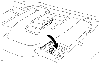
Close the oil filler cap service hole cover.
-
-
ADD ENGINE COOLANT
Standard Capacity Item Radiator Core Thickness [mm] Specified Condition for 2WD 16 11.0 liters (11.6 US qts, 9.7 Imp. qts) 27 11.8 liters (12.5 US qts, 10.4 Imp. qts) for AWD 16 11.1 liters (11.7 US qts, 9.8 Imp. qts) CAUTION:
Do not remove the radiator reservoir cap while the engine and radiator are still hot. Pressurized hot engine coolant and steam may be released and cause serious burns.
Tech Tips
Before adding coolant, turn the A/C switch off.
-
Tighten the radiator drain cock plug.
-
Tighten the 2 cylinder block drain cock plugs.
- Torque:
- 13 N*m { 133 kgf*cm, 10 ft.*lbf }
-
Add TOYOTA Super Long Life Coolant (SLLC) into the radiator reservoir.
Capacity 5.0 liters (5.3 US qts, 4.4 Imp. qts) Tech Tips
-
TOYOTA vehicles are filled with TOYOTA SLLC at the factory. In order to avoid damage to the engine cooling system and other technical problems, only use TOYOTA SLLC or similar high quality ethylene glycol based non-silicate, non-amine, non-nitrite, non-borate coolant with long-life hybrid organic acid technology (coolant with long-life hybrid organic acid technology consists of a combination of low phosphates and organic acids).
-
Please contact any authorized TOYOTA dealer or repairer or another duly qualified and equipped professional for further details.
-
The thermostat open timing can be confirmed by pressing the inlet radiator hose by hand, and checking when the coolant starts to flow inside the hose.
-
-
Further add coolant into the radiator reservoir until it reaches the FULL line.
-
Press the No. 1 and No. 2 radiator hoses several times by hand, and then check the coolant level.
If the coolant level is low, add coolant.
-
Using a 6 mm hexagon wrench, install the vent plug.
- Torque:
- 1.5 N*m { 15 kgf*cm, 13 in.*lbf }
-
Bleed air from the cooling system.
Note
Before starting the engine to warm up the engine, turn the A/C switch off.
-
While idling the engine for approximately 10 minutes, make sure the coolant remains at the FULL line by adding coolant as necessary.
-
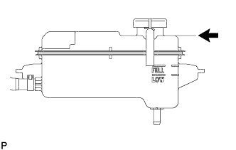
After idling the engine for 10 minutes, add coolant until it reaches the B line.
Capacity Approximately 2.5 to 3.5 liters (2.6 to 3.7 US qts, 2.2 to 3.1 Imp. qts) Text in Illustration B Line Tech Tips
The B line is the lower edge of the inner wall of the filler neck.
-
Close the radiator reservoir cap, and run the engine at 1500 to 2000 rpm for 5 minutes.
CAUTION:
-
Wear protective gloves.
-
Be careful as the radiator hoses are hot.
-
Keep your hands away from the radiator fans.
Tech Tips
The thermostat open timing can be confirmed by pressing the No. 1 radiator hose by hand, and checking when the SLLC starts to flow inside the hose.
-
-
-
Stop the engine and wait until the coolant cools down to ambient temperature.
-
Check the coolant level.
If the coolant level is below the FULL line, add coolant until it reaches the FULL line.
-
-
CONNECT CABLE TO NEGATIVE BATTERY TERMINAL
Note
When disconnecting the cable, some systems need to be initialized after the cable is reconnected Click here.
-
INSPECT FOR OIL LEAK
-
Start the engine. Make sure that there are no oil leaks from the area that was worked on.
-
-
INSPECT FOR COOLANT LEAK
CAUTION:
Do not remove the radiator reservoir cap while the engine and radiator are still hot. Pressurized, hot engine coolant and steam may be released and cause serious burns.
Note
Before each inspection, turn the A/C switch OFF.
-
Fill the radiator with coolant and attach a radiator cap tester.
-
Warm up the engine.
-
Using the radiator cap tester, increase the pressure inside the radiator to 118 kPa (1.2 kgf/cm2, 17 psi), and check that the pressure does not drop.
If the pressure drops, check the hoses, radiator and water pump for leaks. If no external leaks are found, check the heater core, cylinder block and head.
-
-
INSPECT FOR FUEL LEAK
-
Connect the intelligent tester to the DLC3.
-
Turn the engine switch on (IG).
Note
Do not start the engine.
-
Turn the intelligent tester on.
-
Select the following menus: Powertrain / Engine / Active Test / Control the Fuel Pump / Speed.
-
Check the fuel pump operation.
-
Check for pressure in the fuel inlet tube from the fuel line. Check that the sound of fuel flowing in the fuel tank can be heard.
If no sound can be heard, check the integration relay, fuel pump, ECM and wiring connector.
-
-
Check for fuel leaks.
-
Check that there are no fuel leaks anywhere on the system after performing maintenance.
If there is a fuel leak, repair or replace parts as necessary.
-
-
-
INSPECT FOR EXHAUST GAS LEAK
-
If gas is leaking, tighten the areas necessary to stop the leak. Replace the damaged parts as necessary.
-
-
CHECK ENGINE OIL LEVEL
-
Warm up the engine, stop the engine and wait 5 minutes. The oil level should be between the dipstick's low level mark and full level mark.
If low, check for leakage and add oil up to the full level mark.
Note
Do not fill engine oil above the full level mark.
Tech Tips
A certain amount of engine oil will be consumed while driving. In the following situations, oil consumption may increase, and engine oil may need to be refilled in between oil maintenance intervals.
-
When the engine is new, for example directly after purchasing the vehicle or after replacing the engine.
-
If low quality oil or oil of an inappropriate viscosity is used.
-
When driving at high engine speed or with a heavy load, (when towing, or), when driving while accelerating or decelerating frequently.
-
When leaving the idling for a long time, or when driving frequently through heavy traffic.
When judging the amount of oil consumption, keep in mind that the oil may have become diluted, making it difficult to judge the true level accurately.
-
-
-
INSTALL FRONT SUSPENSION MEMBER PROTECTOR LOWER
-
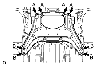
Install the front suspension member protector lower with the 8 bolts.
- Torque:
- 5.5 N*m { 56 kgf*cm, 49 in.*lbf }
-
-
INSTALL NO. 2 ENGINE UNDER COVER
-
Install the No. 2 engine under cover with the 8 bolts.
- Torque:
- for bolt A
- 10 N*m { 102 kgf*cm, 7 ft.*lbf }
- for bolt B
- 27 N*m { 275 kgf*cm, 20 ft.*lbf }
-
-
INSTALL NO. 1 ENGINE UNDER COVER
-
Install the No. 1 engine under cover with the 13 screws and 7 clips.
-
-
INSTALL ENGINE ROOM SIDE COVER RH
-
Install the engine room side cover RH with the 5 clips.
-
-
INSTALL ENGINE ROOM SIDE COVER LH
-
Install the engine room side cover LH with the 5 clips.
-
-
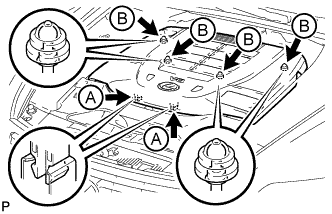
INSTALL AIR CLEANER INLET COVER SUB-ASSEMBLY
-
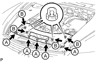
Attach the 4 clips labeled B.
Note
-
Make sure the clips are attached securely.
-
Attaching the clips forcefully or hitting the top of the clips may damage them.
-
-
Install the air cleaner inlet cover sub-assembly with the 5 clips labeled A.
-
-
INSTALL V-BANK COVER SUB-ASSEMBLY
-
Slide the cover from the vehicle front toward the rear of the vehicle to attach the 2 clips labeled A, and then attach the 4 clips labeled B to install the V bank cover sub-assembly.
Note
-
Make sure the clips are attached securely.
-
Attaching the clips forcefully or hitting the top of the clips may damage them.
-
When attaching the clips labeled A, be sure to slide the cover from the front of the vehicle toward the rear of the vehicle.
-
-
-
INSTALL COWL TOP VENTILATOR LOUVER
-

for LHD:
Install the 6 clips and cowl top ventilator louver RH.
Note
If the cowl top ventilator louver RH is not properly installed, water may leak into the engine room and cause malfunctions. Therefore, make sure the cowl top ventilator louver RH is installed properly.
-

for RHD:
Install the 6 clips and cowl top ventilator louver LH.
Note
If the cowl top ventilator louver LH is not properly installed, water may leak into the engine room and cause malfunctions. Therefore, make sure the cowl top ventilator louver LH is installed properly.
-