OIL PUMP (for 2WD) REMOVAL

-
DISCHARGE FUEL SYSTEM PRESSURE
-
REMOVE COWL TOP VENTILATOR LOUVER
-

for LHD:
Remove the 6 clips and cowl top ventilator louver RH.
-

for RHD:
Remove the 6 clips and cowl top ventilator louver LH.
-
-
PRECAUTION
Note
After turning the engine switch off, waiting time may be required before disconnecting the cable from the battery terminal. Therefore, make sure to read the disconnecting the cable from the battery terminal notice before proceeding with work Click here.
-
DISCONNECT CABLE FROM NEGATIVE BATTERY TERMINAL
Note
When disconnecting the cable, some systems need to be initialized after the cable is reconnected Click here.
-
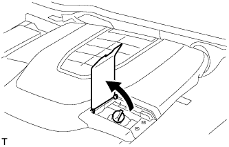
REMOVE V-BANK COVER SUB-ASSEMBLY
-
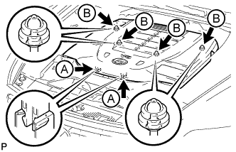
Using both hands, lift the rear side of the cover upwards to detach the 4 clips labeled B. Then slide the cover toward the front of the vehicle to detach the 2 clips labeled A and remove the V-bank cover sub-assembly.
Note
-
The V-bank cover sub-assembly may be damaged if its front and rear are lifted at the same time.
-
When detaching the clips labeled A, be sure to slide the cover toward the front of the vehicle.
-
-
-
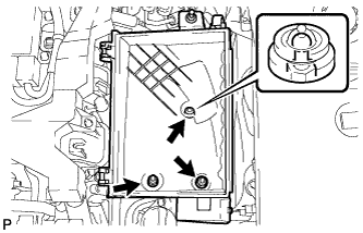
REMOVE AIR CLEANER INLET COVER SUB-ASSEMBLY
-
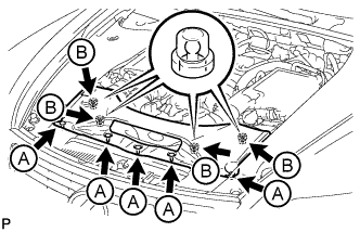
Remove the 5 clips labeled A.
-
Lift up the air cleaner inlet cover sub-assembly to detach the 4 clips labeled B, and remove the air cleaner inlet cover sub-assembly.
-
-
REMOVE NO. 1 AIR CLEANER INLET
-

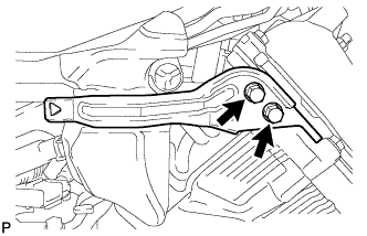
Remove the 2 bolts.
-
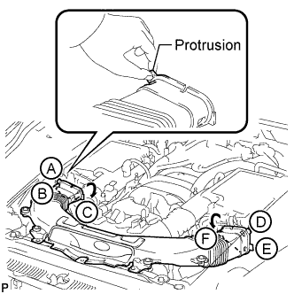
Hold the No. 1 air cleaner inlet by the protrusions labeled A and labeled B, and detach the connections.
-
Rotate the No. 1 air cleaner inlet as shown in the illustration to detach the protrusion labeled C.
-
Hold the No. 1 air cleaner inlet by the protrusions labeled D and labeled E, and detach the connections.
-
Rotate the No. 1 air cleaner inlet as shown in the illustration to detach the protrusion labeled F.
-
-
REMOVE ENGINE ROOM SIDE COVER LH
-
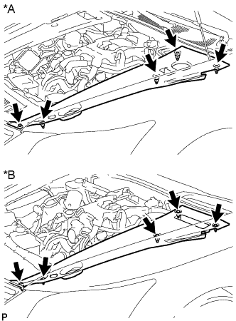
Text in Illustration *A for LHD *B for RHD Remove the 5 clips and engine room side cover LH.
-
-
REMOVE ENGINE ROOM SIDE COVER RH
-
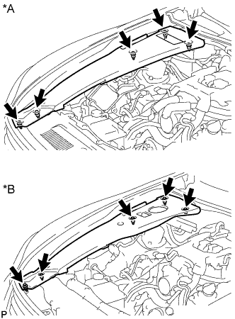
Text in Illustration *A for LHD *B for RHD Remove the 5 clips and engine room side cover RH.
-
-
REMOVE BATTERY CLAMP SUB-ASSEMBLY
-
Remove the nut, battery clamp and 2 clamp bolts.
-
-
REMOVE BATTERY TRAY
-
Remove the battery insulator and battery.
-
Remove the 3 bolts and battery tray.
-
-
REMOVE NO. 1 ENGINE UNDER COVER
-
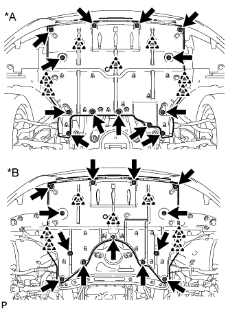
Text in Illustration *A for 2WD *B for AWD Remove the 13 screws, 7 clips and No. 1 engine under cover.
-
-
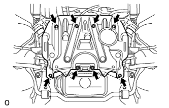
REMOVE NO. 2 ENGINE UNDER COVER
-
Remove the 8 bolts and No. 2 engine under cover.
-
-
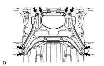
REMOVE FRONT SUSPENSION MEMBER PROTECTOR LOWER
-
Remove the 8 bolts and front suspension member protector lower.
-
-
REMOVE ENGINE UNDER COVER REAR LH
-
Remove the 2 screws and engine under cover rear LH.
-
-
REMOVE ENGINE UNDER COVER REAR RH
Tech Tips
Remove the RH side following the same procedures as the LH side.
-
DRAIN ENGINE OIL
-
Open the oil filler cap service hole cover.
-
Remove the oil filler cap.
-
Remove the oil pan drain plug and drain the engine oil into a container.
-
Install a new gasket and the oil pan drain plug.
- Torque:
- 40 N*m { 408 kgf*cm, 30 ft.*lbf }
-
-
DRAIN ENGINE COOLANT
CAUTION:
Do not remove the radiator reservoir cap and vent plug while the engine and radiator are still hot. Pressurized, hot engine coolant and steam may be released and cause serious burns.
-
Loosen the radiator drain cock plug.
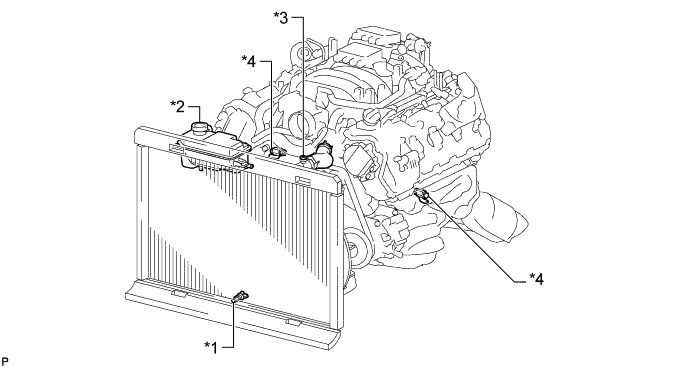
Text in Illustration *1 Radiator Drain Cock Plug *2 Radiator Reservoir Cap *3 Vent Plug *4 Cylinder Block Drain Cock Plug Tech Tips
Collect the coolant in a container and dispose of it according to the regulations in your area.
-
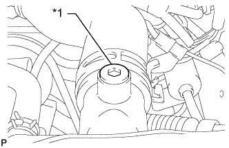
Text in Illustration *1 Vent Plug Remove the radiator reservoir cap, and using a 6 mm hexagon wrench, remove the vent plug.
-
Drain coolant.
-
Loosen the 2 cylinder block drain cock plugs.
-
-
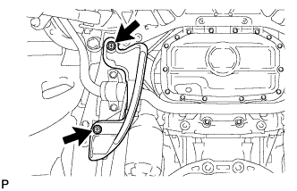
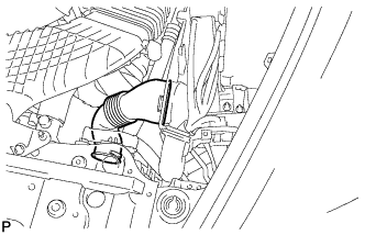
REMOVE INTAKE AIR CONNECTOR PIPE
-
Disconnect the No. 1 and No. 2 ventilation hoses from the intake air connector pipe.
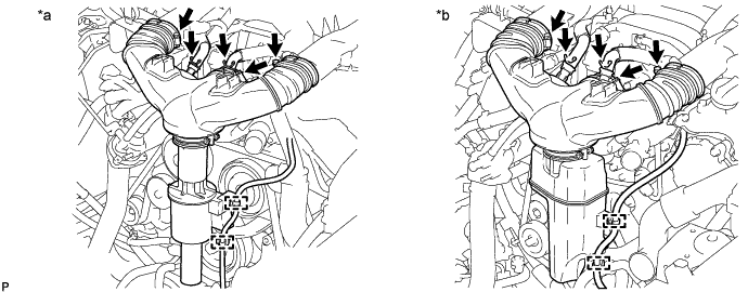
Text in Illustration *a w/ Intake Air Sound Creator *b w/ Intake Air Resonator -
Using a clip remover, detach the 2 wire harness clamps.
-
Loosen the 3 hose clamps, and remove the intake air connector pipe.
-
Remove the intake air sound creator.
Tech Tips
Only perform this procedure when replacement of the intake air sound creator is necessary.
-
Loosen the hose clamp and remove the intake air sound creator.
-
-
-
REMOVE AIR CLEANER ASSEMBLY RH
-
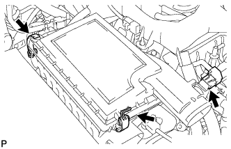
Disconnect the mass air flow meter connector.
-
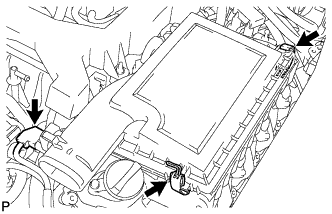
Disconnect the 2 clamps and remove the air cleaner cap RH.
-
Remove the air cleaner filter element from air cleaner case RH.
-
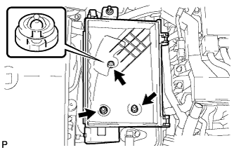
Remove the 2 nuts, clip and air cleaner case RH.
-
-
REMOVE AIR CLEANER ASSEMBLY LH
-
Disconnect the mass air flow meter connector.
-
Disconnect the 2 clamps and remove the air cleaner cap LH.
-
Remove the air cleaner filter element from air cleaner case LH.
-
Remove the 2 nuts, clip and air cleaner case LH.
-
-
REMOVE RADIATOR RESERVOIR ASSEMBLY
-
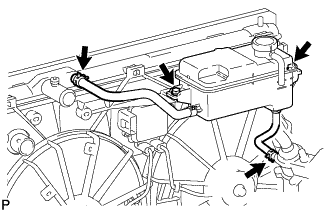
Disconnect the 2 reservoir hoses.
-
Remove the 2 bolts and radiator reservoir assembly.
-
-
REMOVE V-RIBBED BELT
-

Rotate the tensioner pulley counterclockwise to loosen the belt tension.
Tech Tips
The pulley bolt for the belt tensioner has a left-handed thread.
-
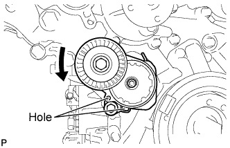
While turning the belt tensioner counterclockwise, align the holes. Insert a bar with a diameter of 5 mm (0.197 in.) into the holes to fix the belt tensioner in place.
-
-
Remove the V-ribbed belt.
-
-
DISCONNECT NO. 1 RADIATOR HOSE
-
DISCONNECT NO. 2 RADIATOR HOSE
-
REMOVE ENGINE ROOM ECU OUTLET DUCT
-
Remove the engine room ECU outlet duct.
-
-
REMOVE NO. 2 ENGINE COVER (for LHD)
-
Remove the 4 nuts and No. 2 engine cover.
-
-
REMOVE SKID CONTROL ECU BRACKET
-
for LHD: Click here
-
for RHD: Click here
-
-
DISCONNECT ENGINE WIRE
-
for Engine Room LH Side:
-
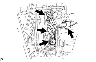
Remove the ECM box cover (upper).
-
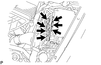
Disconnect the 3 ECT connectors and 4 ECM connectors from the ECM box.
-
Disconnect the camshaft timing control valve connector.
-
Disconnect the 4 ignition coil connectors.
-
Disconnect the 2 VVT sensor connectors.
-
Disconnect the fuel pump connector (for high pressure).
-
Disconnect the No. 8 engine wire connector.
-
Remove the 2 bolts and disconnect the clamp and 2 clamp brackets.
-
Disconnect the engine coolant temperature sensor connector.
-
Disconnect the engine oil pressure sensor connector.
-
Disconnect the 2 camshaft timing control motor connectors (for Bank 1).
-
Detach the clamp and disconnect the cooler compressor connector.
-
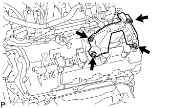
Remove the 3 bolts and disconnect the 3 clamps and ground wire.
-
Remove the bolt and clamp bracket.
-
-
for Engine Room RH Side:
-
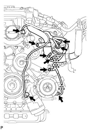
Detach the clamp and disconnect the 3 connectors from the front controller.
-
Remove the 2 nuts and disconnect the wires from the No. 1 engine room junction block.
-
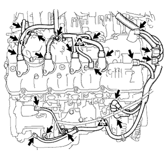
Disconnect the camshaft timing control valve connector.
-
Disconnect the 4 ignition coil connectors.
-
Disconnect the 2 VVT sensor connectors.
-
Disconnect the fuel pump connector (for high pressure).
-
Disconnect the engine wire connector.
-
Disconnect the 2 camshaft timing control motor connectors (for Bank 2).
-
Disconnect the camshaft position sensor connector.
-
Remove the nut and disconnect the generator wire and connector.
-
Remove the nut and disconnect the starter wire and connector.
-
Disconnect the crankshaft position sensor connector.
-
Disconnect the engine oil level sensor connector.
-
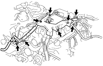
Remove the 3 bolts, and disconnect the 3 clamp brackets and 2 clamps.
-
-
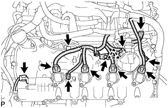
Remove the bolt and disconnect the ground wire.
-
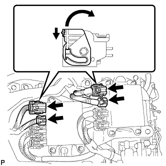
Disconnect the 4 injector connectors as shown in the illustration.
-
Disconnect the No. 1 vacuum switching valve connector.
-
Disconnect the intake air control valve actuator connector.
-
Remove the 2 bolts and disconnect the 2 clamp brackets and clamp.
-
Remove the 4 nuts and disconnect the engine wire.
-
-
REMOVE FRONT EXHAUST PIPE ASSEMBLY
-
REMOVE FRONT STABILIZER BAR
-
REMOVE FRONT SUSPENSION MEMBER REINFORCEMENT LH
-
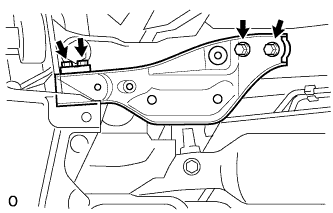
Remove the 4 bolts and front suspension member reinforcement LH from the vehicle.
-
-
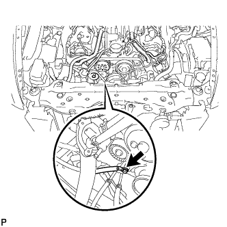
REMOVE STEERING SLIDING YOKE WITH SHAFT SUB-ASSEMBLY (for LHD with VGRS)
-
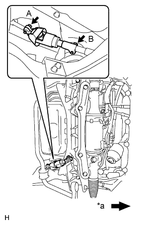
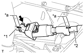
Text in Illustration *a Front of the vehicle Loosen bolt A and remove bolt B, then slide the steering sliding with shaft yoke.
Note
-
Do not remove bolt A.
-
Do not separate the steering sliding with shaft yoke from the power steering link.
-
-
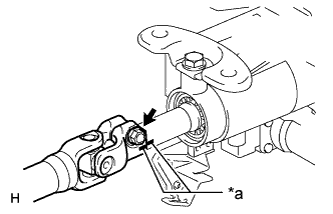
Text in Illustration *1 No. 2 steering intermediate shaft *2 Power steering link *a Matchmark Put matchmarks on the steering sliding with shaft yoke, No. 2 steering intermediate shaft and power steering link.
-
Remove the bolt and the steering sliding with shaft yoke from the power steering link.
-
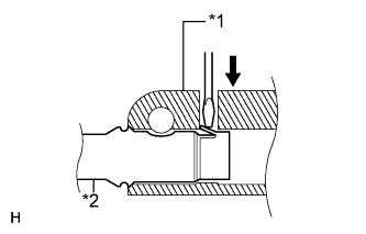
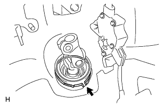
Text in Illustration *1 Steering sliding with shaft yoke *2 No. 2 steering intermediate shaft Separate the steering sliding with shaft yoke from the No. 2 steering intermediate shaft.
Tech Tips
Insert a screwdriver or equivalent into the yoke's hole. Hold down the intermediate shaft's claw and remove the No. 2 steering intermediate shaft. If the claw is damaged, remove the claw. The intermediate shaft does not have to be replaced.
-
-
REMOVE STEERING SLIDING YOKE WITH SHAFT SUB-ASSEMBLY (for LHD without VGRS)
-
Text in Illustration *a Front of the Vehicle Loosen bolt A and remove bolt B, then slide the steering sliding with shaft yoke.
Note
-
Do not remove bolt A.
-
Do not separate the steering sliding with shaft yoke from the intermediate shaft.
-
-
Text in Illustration *1 No. 2 steering intermediate shaft *2 Intermediate shaft *a Matchmark Put matchmarks on the steering sliding with shaft yoke, No. 2 steering intermediate shaft and intermediate shaft.
-
Remove the bolt and the steering sliding with shaft yoke from the steering intermediate shaft.
-
Text in Illustration *1 Steering sliding with shaft yoke *2 No. 2 steering intermediate shaft Separate the steering sliding with shaft yoke from the No. 2 steering intermediate shaft.
Tech Tips
Insert a screwdriver or equivalent into the yoke's hole. Hold down the intermediate shaft's claw and remove the intermediate shaft. If the claw is damaged, remove the claw. The intermediate shaft does not have to be replaced.
-
-
REMOVE NO. 2 STEERING INTERMEDIATE SHAFT ASSEMBLY
-
Text in Illustration *a Matchmark Put matchmarks on the No. 2 steering intermediate shaft and the steering column.
-
Remove the bolt.
-
Remove the clamp and No. 2 steering intermediate shaft.
-
-
REMOVE NO. 2 EXHAUST MANIFOLD HEAT INSULATOR
-
Disconnect the air fuel ratio sensor connector.
-
Remove the 3 bolts and No. 2 exhaust manifold heat insulator.
-
-
REMOVE EXHAUST MANIFOLD SUB-ASSEMBLY LH
-
Remove the 8 nuts and exhaust manifold LH.
-
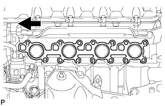
Remove the gasket.
Text in Illustration 
Front
-
-
DISCONNECT COOLER COMPRESSOR ASSEMBLY
-
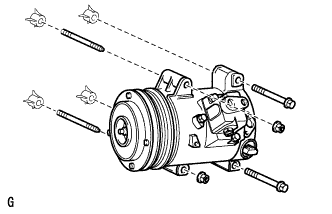
Remove the 2 bolts, 2 nuts and 2 stud bolts and disconnect the cooler compressor assembly.
Tech Tips
It is not necessary to completely remove the cooler compressor assembly. With the hoses connected to the cooler compressor assembly, hang the cooler compressor assembly on the vehicle body with a rope.
-
-
REMOVE ENGINE OIL LEVEL DIPSTICK GUIDE
-
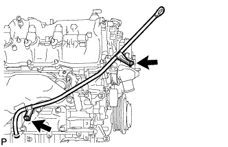
Remove the engine oil level dipstick.
-
Remove the 2 bolts and engine oil level dipstick guide.
-
-
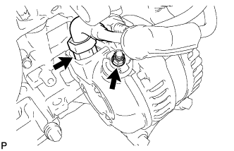
REMOVE GENERATOR ASSEMBLY
-
Remove the nut, and disconnect the harness from the +B terminal.
-
Disconnect the generator connector.
-
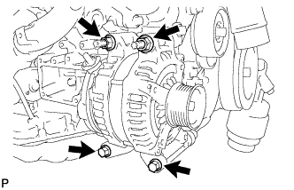
Remove the 2 bolts and 2 nuts.
-
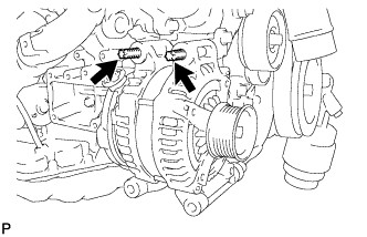
Using an E8 "TORX" socket wrench, remove the 2 stud bolts and generator.
-
-
REMOVE INJECTOR DRIVER
-
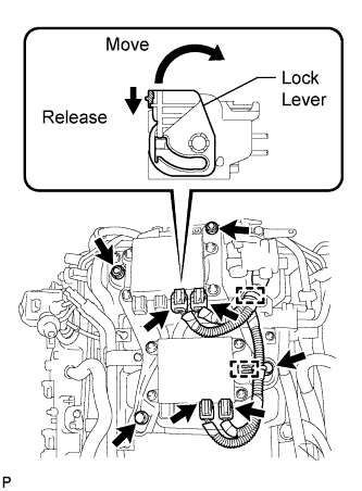
Disconnect the 4 injector driver connectors.
Tech Tips
To disconnect the injector driver connectors, push the claw downward and move the lock lever to release the lock.
-
Disconnect the 2 clamps from the injector driver.
-
Remove the 2 bolts, 2 nuts and injector driver from the intake manifold.
-
-
REMOVE NO. 1 ENGINE COVER
-
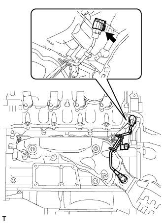
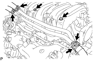
REMOVE WATER BY-PASS PIPE SUB-ASSEMBLY
-
Slide the 4 clamps and disconnect the heater water inlet hose, heater water outlet hose, water inlet hose, and No. 3 water by-pass hose from the water by-pass pipe sub-assembly.
-
Remove the 2 bolts and water by-pass pipe sub-assembly.
-
-
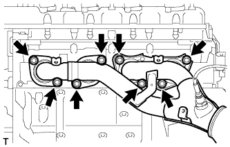
REMOVE INTAKE MANIFOLD
-
Disconnect the No. 1 ventilation hose from the intake manifold.
-
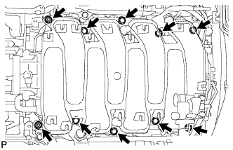
Remove the 8 bolts, 2 nuts and intake manifold.
-
Remove the 2 gaskets from the intake manifold.
-
-
REMOVE NO. 3 ENGINE COVER
-
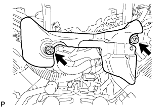
Remove the 2 bolts and bracket.
-
Remove the 2 clips and No. 3 engine cover.
-
-
REMOVE ENGINE COVER SUB-ASSEMBLY
-
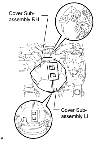
Detach the 5 claws and remove the engine cover LH and RH from the fuel pump.
-
-
REMOVE FUEL PRESSURE PULSATION DAMPER ASSEMBLY
-
Remove the bolt and bracket.
-
Disconnect the connector from the delivery pipe.
-
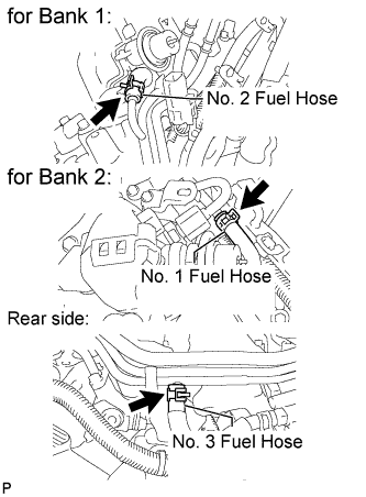
Disconnect the 3 fuel hoses.
-
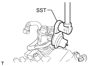
Using SST, loosen the 2 fuel pressure pulsation dampers.
- SST
- 09612-24014 ( 09617-24011 )
-
Remove the 2 clamp bolts shown in the illustration.
-
Remove the 2 pulsation dampers, 4 gaskets and No. 1 fuel pipe.
-
-
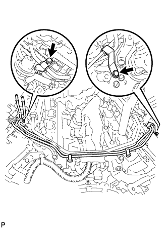
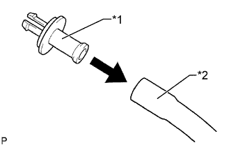
REMOVE NO. 3 FUEL PIPE SUB-ASSEMBLY
-
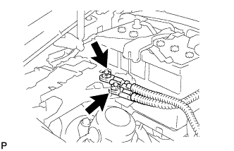
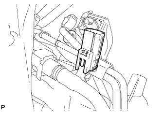
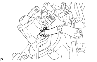
Remove the fuel pump connector.
-
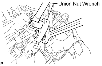
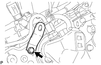
Fix the union bolt on the fuel pump side in place with a 21 mm wrench. Using a 19 mm union nut wrench, loosen the union nut and disconnect the fuel pipe from the fuel pump.
Note
Do not loosen the union bolt on the fuel pump side. If the union bolt is accidentally loosened, replace the fuel pump.
-
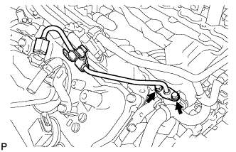
Remove the 2 bolts on the delivery pipe side and remove the fuel pipe.
-
Remove the O-ring, backup ring and E-ring from the fuel pipe.
-
-
REMOVE NO. 2 FUEL PIPE SUB-ASSEMBLY
Tech Tips
The removal procedures are the same as the No. 3 fuel pipe.
-
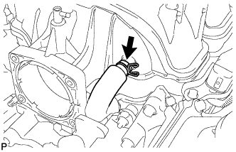
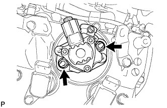
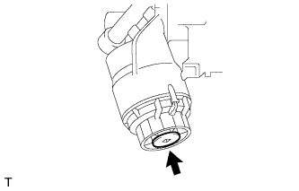
REMOVE FUEL PUMP ASSEMBLY (for High Pressure)
-
Remove the 2 nuts, fuel pump and fuel pump insulator.
-
Disconnect the fuel hose from the fuel pump.
-
-
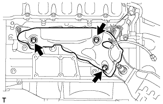
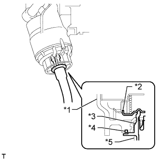
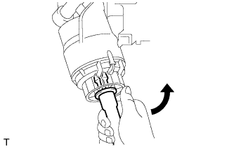
REMOVE WATER INLET HOUSING
-
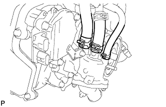
Using needle-nose pliers, grip the claws of the clips and slide the clips to disconnect the water by-pass hoses and water inlet hose.
-
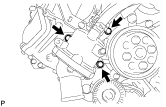
Remove the 3 bolts, water inlet housing and gasket.
-
-
REMOVE WATER PUMP PULLEY
-
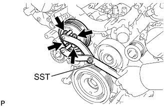
Using SST, hold the water pump pulley.
- SST
- 09960-10010 ( 09962-01000, 09963-01000 )
-
Remove the 4 bolts and water pump pulley.
-
-
REMOVE NO. 2 IDLER PULLEY SUB-ASSEMBLY
-
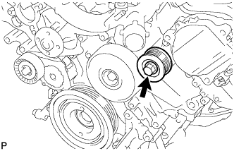
Remove the bolt and No. 2 idler pulley sub-assembly.
-
-
REMOVE NO. 1 IDLER PULLEY SUB-ASSEMBLY
-
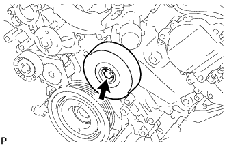
Remove the bolt and No. 1 idler pulley sub-assembly.
-
-
REMOVE V-RIBBED BELT TENSIONER ASSEMBLY
-
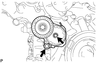
Remove the standard bolt, 6 mm hexagon wrench bolt and belt tensioner.
-
-
REMOVE FRONT WATER BY-PASS JOINT
-
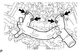
Remove the 4 nuts, water by-pass joint and 2 gaskets.
-
-
REMOVE CAMSHAFT TIMING CONTROL WITH EDU MOTOR ASSEMBLY LH (for Bank 1)
-
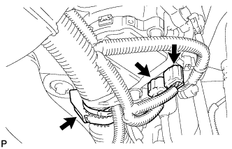
Disconnect the 2 camshaft timing control with EDU motor assembly LH connectors and engine wire clamp.
-
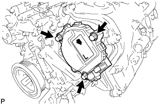
Remove the 3 bolts and camshaft timing control with EDU motor assembly LH.
Note
Do not allow foreign matter to contact the oil seal face of the camshaft timing control with EDU motor assembly LH (connecting surface with timing chain cover).
-
Remove the O-ring from the timing chain cover.
-
-
REMOVE CAMSHAFT TIMING CONTROL WITH EDU MOTOR ASSEMBLY RH (for Bank 2)
-
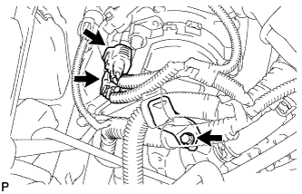
Disconnect the 2 camshaft timing control with EDU motor assembly RH connectors.
-
Remove the bolt and engine wire bracket.
-
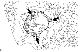
Remove the 3 bolts and camshaft timing control with EDU motor assembly RH.
Note
Do not allow foreign matter to contact the oil seal face of the camshaft timing control with EDU motor assembly RH (connecting surface with timing chain cover).
-
Remove the O-ring from the timing chain cover.
-
-
REMOVE OIL FILTER ELEMENT
-
Text in Illustration *1 Pipe *2 Hose Connect a hose with an inside diameter of 15 mm (0.591 in.) to the pipe.
-
Remove the oil filter drain plug.
-
Text in Illustration *1 Oil Filter Cap *2 Valve *3 Pipe *4 O-Ring *5 Hose Install the pipe to the oil filter cap.
Note
If the O-ring is removed with the drain plug, install the O-ring together with the pipe.
Tech Tips
Use a container to catch the draining oil.
-
Check that oil is drained from the oil filter. Then disconnect the pipe and remove the O-ring as shown in the illustration.
-
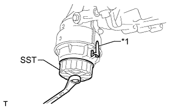
Text in Illustration *1 Oil Filter Bracket Clip Using SST, remove the oil filter cap.
- SST
- 09228-06501
Note
Do not remove the oil filter bracket clip.
-
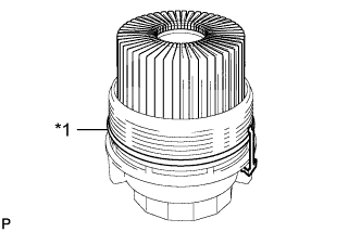
Text in Illustration *1 O-Ring Remove the oil filter element and O-ring from the oil filter cap.
Note
Be sure to remove the O-ring (for the cap) by hand, without using any tools, to prevent damage to the groove.
-
-
REMOVE OIL FILTER BRACKET
-
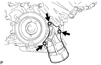
Remove the 3 bolts, filter bracket and 2 gaskets.
-
-
REMOVE RESONATOR BRACKET SUB-ASSEMBLY
-
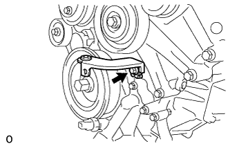
Remove the bolt and resonator bracket sub-assembly.
-
-
REMOVE CRANKSHAFT PULLEY
-
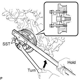
Using SST, loosen the crankshaft pulley set bolt.
- SST
- 09213-54015 ( 90119-08216 )
- 09330-00021
-
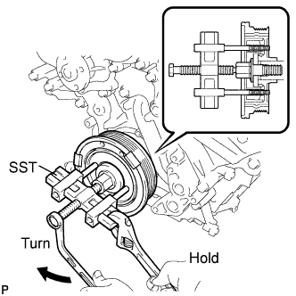
Using the pulley set bolt and SST, remove the crankshaft pulley.
- SST
- 09950-50013 ( 09951-05010, 09952-05010, 09953-05010, 09954-05011 )
-
-
REMOVE IGNITION COIL ASSEMBLY
-
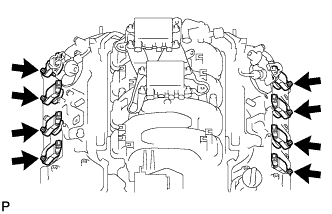
Disconnect the 8 ignition coil assembly connectors.
-
Remove the 8 bolts.
-
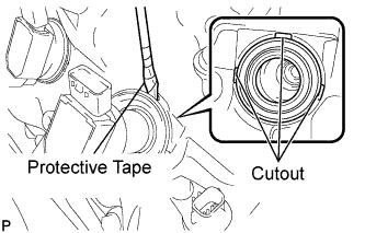
Using a screwdriver, pry up each spark plug tube gasket at the cutouts to remove the 8 ignition coil assemblies together with the 8 spark plug tube gaskets.
Note
Do not damage the cylinder head cover when removing the spark plug tube gasket.
Tech Tips
Tape the screwdriver tip before use.
-
-
REMOVE CYLINDER HEAD COVER SUB-ASSEMBLY LH
-
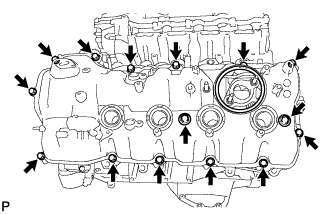
Remove the 15 bolts, 2 seal washers, cylinder head cover and gasket.
Tech Tips
Make sure the removed parts are returned to the same places they were removed from.
-
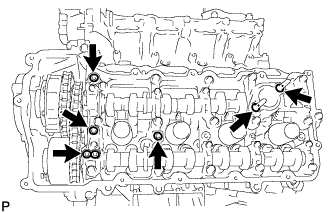
Remove the 4 gaskets and 2 O-rings from the camshaft bearing caps (No. 2, No. 3, No. 7).
-
-
REMOVE CYLINDER HEAD COVER SUB-ASSEMBLY RH
-
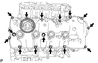
Remove the 15 bolts, 2 seal washers, cylinder head cover and gasket.
Tech Tips
Make sure the removed parts are returned to the same places they were removed from.
-
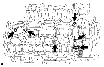
Remove the 4 gaskets and 2 O-rings from the camshaft bearing caps (No. 1, No. 3, No. 6).
-
-
REMOVE TIMING CHAIN COVER SUB-ASSEMBLY
-
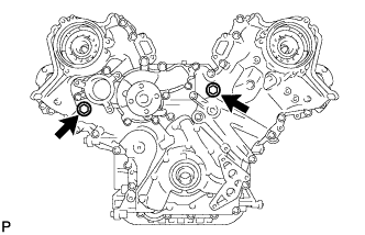
Remove the 2 plugs and 2 gaskets.
-
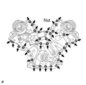
Remove the 30 bolts and nut shown in the illustration.
-
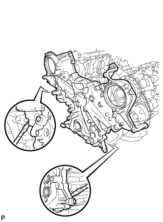
Remove the timing chain cover by prying between the timing chain cover and cylinder head and cylinder block with a screwdriver as shown in the illustration.
Note
Be careful not to damage the contact surfaces of the cylinder head, cylinder block and chain cover.
Tech Tips
Tape the screwdriver tip before use.
-
Remove the oil pump gasket from the cylinder block.
-
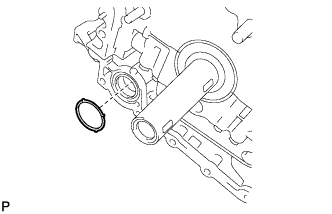
Remove the O-ring from the cylinder block.
-
-
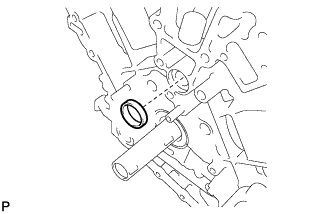
REMOVE WATER INLET PIPE
-
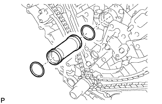
Remove the water inlet pipe.
-
Remove the 2 O-rings from the water inlet pipe.
-