COOLING FAN ECU ON-VEHICLE INSPECTION

-
CHECK COOLING FAN ECU
-
Remove the front controller cover.
-
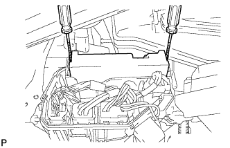
Using 2 screwdrivers, detach the 2 claws and disconnect the front controller.
Tech Tips
Tape the screwdriver tips before use.
-
Check the resistance of the wire harness between the front controller B14-22 (FAN1) and cooling fan ECU A9-2 (SI).
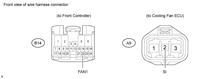
Standard resistance Tester Connection Specified Condition B14-22 (FAN1) - A9-2 (SI) Below 1 Ω B14-22 (FAN1) - Body ground
A9-2 (SI) - Body ground
10 kΩ or higher If the result is not as specified, repair or replace the wire harness or connector.
-
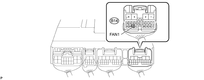
Check the output signal from the front controller.
Tech Tips
Be sure to perform the inspection when the engine coolant temperature is less than 92°C (198°F).
-
Set the oscilloscope probe to the terminal B14-22 (FAN1) of the front controller.
-
Connect the intelligent tester to the DLC3.
-
Using the intelligent tester, check the waveform.
Tech Tips
Select the following menu items: Power train / Engine / Active Test / Cooling Fan.
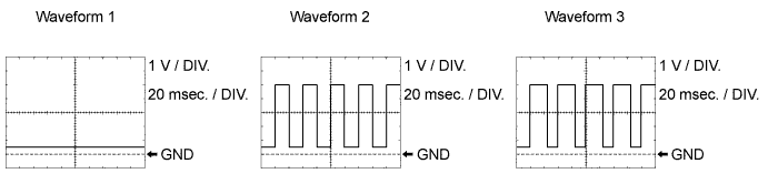
Standard waveform Condition Input Signal Engine stopped
(Engine switch on (IG))
Waveform 1
(Duty ratio 0%)
Engine idling
(A/C OFF)
Waveform 1
(Duty ratio 0%)
Engine idling
(A/C ON)
Waveform 2
(Duty ratio 50 to 70%)
Engine idling
(Engine coolant temperature sensor connector disconnected)
Waveform 3
(Duty ratio 60 to 70%)
If the output signal is abnormal, there is a malfunction in the ECM or front controller.
-
-
Check the input voltage.
-
Disconnect the cooling fan ECU connector.
-
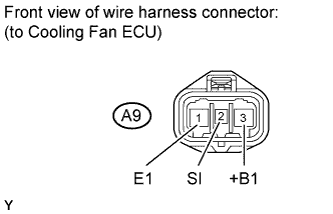
Turn the engine switch on (IG). Check the voltage of the A9-3 (+B1) terminal on the wire harness side.
Standard voltage 11 to 14 V If the result is not as specified, check the power source system (H-fuse, fuse, wire harness and relay).
-
Connect the cooling fan ECU connector.
-
-
Check wire harness (cooling fan ECU and body ground).
-
Disconnect the cooling fan ECU connector.
-
Measure the resistance of the A9-1 (E1) and body ground.
Standard resistance Below 1 Ω If the result is not as specified, check the wire harness or connector.
-
Connect the cooling fan ECU connector.
-
-
Check the cooling fan motor Click here.
If the result is not as specified, replace the cooling fan motor.
-
Check the cooling fan motor operation.
-
Disconnect the cooling fan ECU connector.
-
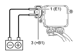
Connect the battery to the cooling fan ECU at terminals 3 (+B1) and 1 (E1).
-
Check that the cooling fan motor rotates.
If it does not operate, replace the cooling fan ECU.
-
-