PURGE VALVE REMOVAL

-
REMOVE AIR CLEANER INLET COVER SUB-ASSEMBLY
-
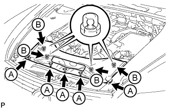
Remove the 5 clips labeled A.
-
Lift up the air cleaner inlet cover sub-assembly to detach the 4 clips labeled B, and remove the air cleaner inlet cover sub-assembly.
-
-
REMOVE ENGINE ROOM SIDE COVER LH
-
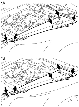
Text in Illustration *A for LHD *B for RHD Remove the 5 clips and engine room side cover LH.
-
-
REMOVE ENGINE ROOM SIDE COVER RH
-
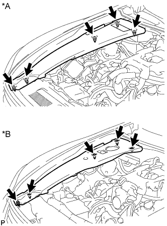
Text in Illustration *A for LHD *B for RHD Remove the 5 clips and engine room side cover RH.
-
-
REMOVE V-BANK COVER SUB-ASSEMBLY
-
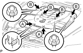
Using both hands, lift the rear side of the cover upwards to detach the 4 clips labeled B. Then slide the cover toward the front of the vehicle to detach the 2 clips labeled A and remove the V-bank cover sub-assembly.
Note
-
The V-bank cover sub-assembly may be damaged if its front and rear are lifted at the same time.
-
When detaching the clips labeled A, be sure to slide the cover toward the front of the vehicle.
-
-
-
REMOVE NO. 1 AIR CLEANER INLET
-

Remove the 2 bolts.
-
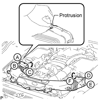
Hold the No. 1 air cleaner inlet by the protrusions labeled A and labeled B, and detach the connections.
-
Rotate the No. 1 air cleaner inlet as shown in the illustration to detach the protrusion labeled C.
-
Hold the No. 1 air cleaner inlet by the protrusions labeled D and labeled E, and detach the connections.
-
Rotate the No. 1 air cleaner inlet as shown in the illustration to detach the protrusion labeled F.
-
-
REMOVE INTAKE AIR CONNECTOR PIPE
-
Disconnect the No. 1 and No. 2 ventilation hoses from the intake air connector pipe.
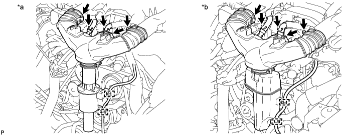
Text in Illustration *a w/ Intake Air Sound Creator *b w/ Intake Air Resonator -
Using a clip remover, detach the 2 wire harness clamps.
-
Loosen the 3 hose clamps, and remove the intake air connector pipe.
-
Remove the intake air sound creator.
Tech Tips
Only perform this procedure when replacement of the intake air sound creator is necessary.
-
Loosen the hose clamp and remove the intake air sound creator.
-
-
-
REMOVE AIR CLEANER CAP SUB-ASSEMBLY LH
-
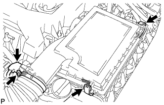
Disconnect the mass air flow meter connector.
-
Remove the 2 clamps, loosen the hose clamp and remove the air cleaner cap sub-assembly LH.
-
-
REMOVE AIR CLEANER CAP SUB-ASSEMBLY RH
-
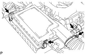
Disconnect the mass air flow meter connector.
-
Remove the 2 clamps, loosen the hose clamp and remove the air cleaner cap sub-assembly RH.
-
-
DISCONNECT ENGINE WIRE (for LHD)
Tech Tips
Fix the disconnected harnesses, etc. in place with tape or equivalent so that they do not interfere.
-
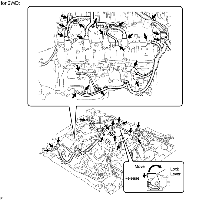
for 2WD:
-
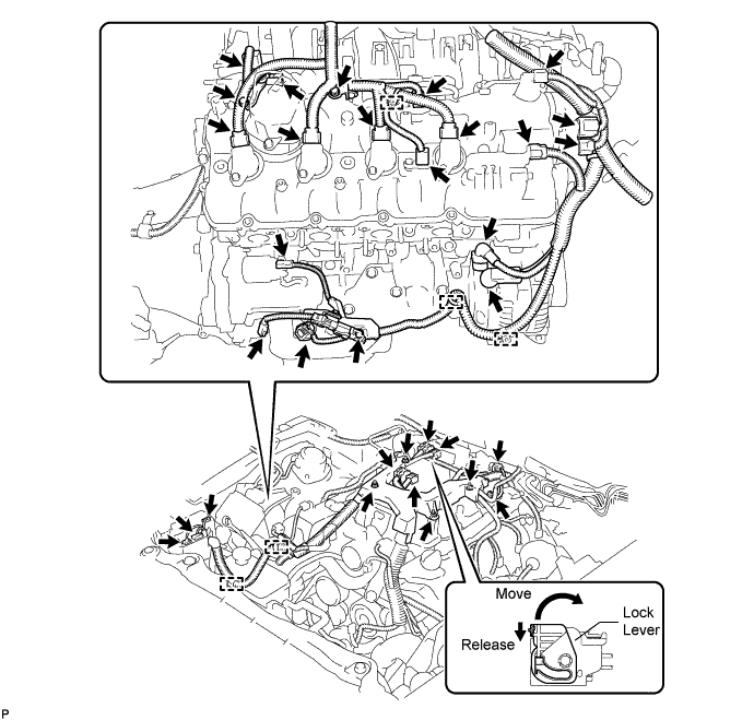
Disconnect the engine wire harness connectors.
Tech Tips
To disconnect the injector driver connectors, push the claw downward and move the lock lever to release the lock.
-
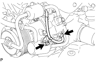
Remove the nut and disconnect the engine wire harness from the +B terminal of the generator assembly.
-
Using a clip remover, disconnect the 7 engine wire harness clamps.
-
Remove the nut and disconnect the engine wire from the fusible link block assembly.
-
Remove the 3 bolts and 3 engine wire harness clamp brackets.
-
Remove the 4 nuts and disconnect the engine wire harness.
-
-
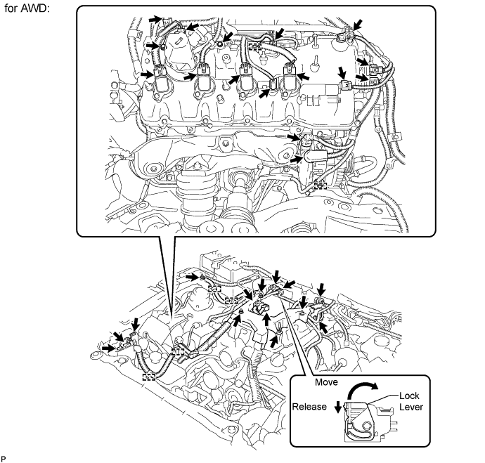
for AWD:
-
Disconnect the engine wire harness connectors.
Tech Tips
To disconnect the injector driver connectors, push the claw downward and move the lock lever to release the lock.
-
Remove the nut and disconnect the engine wire harness from the +B terminal of the generator assembly.
-
Using a clip remover, disconnect the 4 engine wire harness clamps.
-
Remove the 2 bolts and 2 engine wire harness clamp brackets.
-
Remove the 4 nuts and disconnect the engine wire harness.
-
-
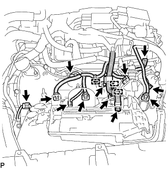
Disconnect the camshaft timing control valve connector.
-
Disconnect the 4 ignition coil connectors.
-
Disconnect the 2 VVT sensor connectors.
-
Disconnect the fuel pump connector (for high pressure).
-
Disconnect the No. 8 engine wire connector.
-
Remove the 2 bolts and disconnect the clamp and 2 clamp brackets.
-
Disconnect the engine coolant temperature sensor connector.
-
Disconnect the oil pressure sensor connector.
-
Disconnect the 2 camshaft timing control motor connectors (for Bank 1).
-
Remove the 3 bolts and disconnect the 3 clamps and 3 ground wires.
-
Remove the bolt and clamp bracket.
-
Remove the bolt and disconnect the wire harness bracket.
-
Disconnect the cooler compressor connector.
-
-
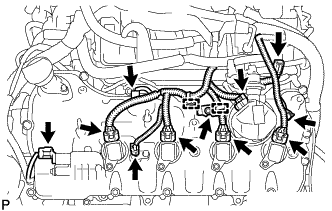
DISCONNECT ENGINE WIRE (for RHD)
Tech Tips
Fix the disconnected harnesses, etc. in place with tape or equivalent so that they do not interfere.
-
Disconnect the engine wire harness connectors.
Tech Tips
To disconnect the injector driver connectors, push the claw downward and move the lock lever to release the lock.
-
Remove the nut and disconnect the engine wire harness from the +B terminal of the generator assembly.
-
Using a clip remover, disconnect the 5 engine wire harness clamps.
-
Remove the 3 bolts and 3 engine wire harness clamp brackets.
-
Remove the 4 nuts and disconnect the engine wire harness.
-
Disconnect the camshaft timing control valve connector.
-
Disconnect the 4 ignition coil connectors.
-
Disconnect the 2 VVT sensor connectors.
-
Disconnect the fuel pump connector (for high pressure).
-
Disconnect the No. 8 engine wire connector.
-
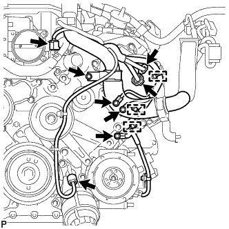
Remove the 2 bolts and 2 clamp brackets.
-
Using a clip remover, detach the 3 engine harness clamps.
-
Remove the nut and disconnect the engine wire from the fusible link block assembly.
-
Disconnect the engine coolant temperature sensor connector.
-
Disconnect the oil pressure sensor connector.
-
Disconnect the 2 camshaft timing control motor connectors (for Bank 1).
-
Remove the 3 bolts and disconnect the 3 clamps and 3 ground wires.
-
Remove the bolt and clamp bracket.
-
Remove the bolt and disconnect the wire harness bracket.
-
Disconnect the cooler compressor connector.
-
-
REMOVE PURGE VSV
-
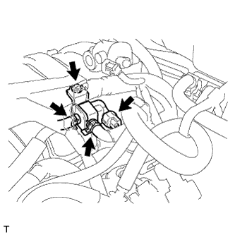
Disconnect the purge VSV connector.
-
Disconnect the 2 purge line hoses from the purge VSV.
-
Remove the bolt and purge VSV.
-