CYLINDER BLOCK INSPECTION

-
INSPECT NO. 1 OIL NOZZLE SUB-ASSEMBLY
-
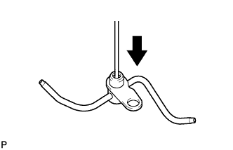
Push the check valve with a pin to check if it is stuck.
If stuck, replace the oil nozzle.
-
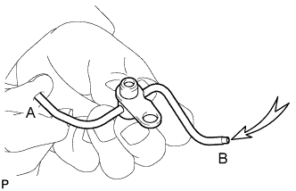
While covering A, apply air into B. Then check the oil nozzle for damage or clogging.
If there is an air leak, clean or replace the oil nozzle.
Tech Tips
Cover B and apply air into A. Perform the check again.
-
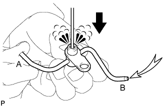
Push the check valve while covering A, and apply air into B. Check that air passes through the oil nozzle.
If air cannot pass through, clean or replace the oil nozzle.
Tech Tips
Cover B and, while pushing the check valve, apply air into A. Perform the check again.
-
-
INSPECT CYLINDER BLOCK FOR WARPAGE
-
Using a precision straightedge and feeler gauge, measure the warpage of the contact surface of the cylinder head gasket.
Maximum warpage 0.07 mm (0.0028 in.) If the warpage is greater than the maximum, replace the cylinder block.
-
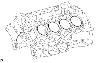
Visually check the cylinder for vertical scratches.
If necessary, replace the cylinder block.
-
-
INSPECT CYLINDER BORE
-
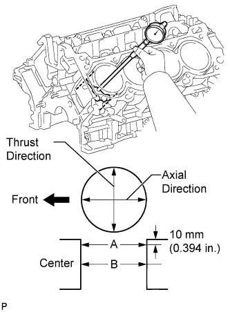
Using a cylinder gauge, measure the cylinder bore diameter at positions A and B in the thrust and axial directions.
Standard diameter 94.000 to 94.012 mm (3.7008 to 3.7013 in.) Maximum diameter 94.200 mm (3.7087 in.) If the diameter is greater than the maximum, replace the cylinder block.
-
-
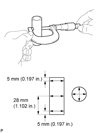
INSPECT PISTON SUB-ASSEMBLY WITH PIN
-
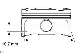
Using a micrometer, measure the piston diameter at a position that is 10.7 mm (0.421 in.) downward from the center of the piston pin hole (refer to the illustration).
Standard diameter 93.955 to 93.965 mm (3.6990 to 3.6994 in.) Minimum diameter 93.830 mm (3.6941 in.)
-
-
INSPECT PISTON OIL CLEARANCE
-
Measure the cylinder bore diameter in the thrust direction.
-
Subtract the piston diameter measurement from the cylinder bore diameter measurement.
Standard oil clearance 0.035 to 0.057 mm (0.0014 to 0.0022 in.) Maximum oil clearance 0.370 mm (0.0146 in.) If the oil clearance is greater than the maximum, replace all the pistons. If necessary, replace the cylinder block.
-
-
INSPECT RING GROOVE CLEARANCE
-
Using a feeler gauge, measure the clearance between a new piston ring and the wall of the ring groove.
Standard ring groove clearance Item Specified Condition No. 1 0.020 to 0.070 mm (0.0008 to 0.0028 in.) No. 2 0.020 to 0.060 mm (0.0008 to 0.0024 in.) Oil 0.020 to 0.070 mm (0.0008 to 0.0028 in.) If the clearance is not as specified, replace the piston.
-
-
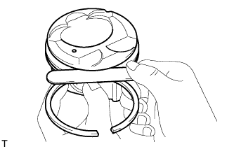
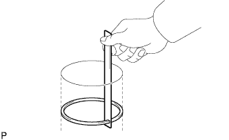
INSPECT PISTON RING END GAP
-
Insert the piston ring into the cylinder bore.
-
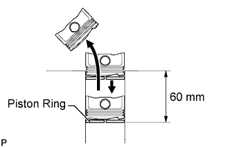
Using a piston, push the piston ring a little beyond the bottom of the ring travel, 60 mm (2.362 in.) from the top of the cylinder block.
-
Using a feeler gauge, measure the end gap.
Standard end gap Item Specified Condition No. 1 0.23 to 0.33 mm (0.0091 to 0.0130 in.) No. 2 0.35 to 0.45 mm (0.0138 to 0.0177 in.) Oil 0.10 to 0.20 mm (0.00394 to 0.00787 in.) Maximum end gap Item Specified Condition No. 1 0.40 mm (0.0157 in.) No. 2 0.50 mm (0.0197 in.) Oil 0.45 mm (0.0177 in.) If the end gap is greater than the maximum, replace the piston ring. If the end gap is greater than the maximum even with a new piston ring, replace the cylinder block.
-
-
INSPECT PISTON PIN OIL CLEARANCE
Tech Tips
There is only 1 type of supply part for piston with pin sub-assembly.
-
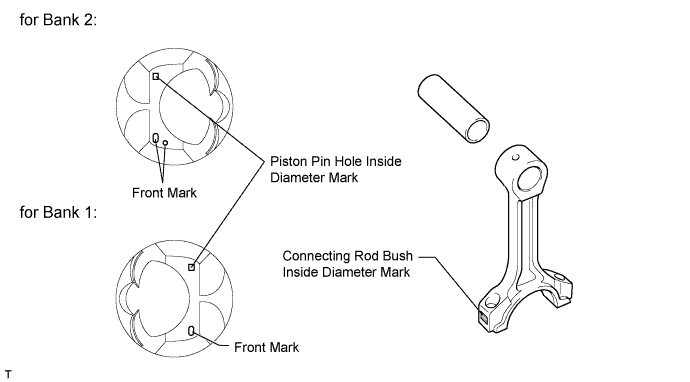
Check each mark on the piston, piston pin and connecting rod.
-
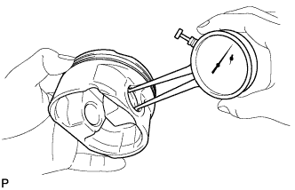
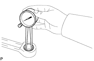
Using a caliper gauge, measure the inside diameter of the piston pin hole.
Standard piston pin hole inside diameter Mark Specified Condition A 21.998 to 22.001 mm (0.8661 to 0.8662 in.) B 22.002 to 22.004 mm (0.8662 to 0.8663 in.) C 22.005 to 22.007 mm (0.8663 to 0.8664 in.) -
Using a micrometer, measure the piston pin diameter.
Standard piston pin diameter Mark Specified Condition A 21.997 to 22.000 mm (0.8660 to 0.8661 in.) B 22.001 to 22.003 mm (0.8662 to 0.8663 in.) C 22.004 to 22.006 mm (0.8663 to 0.8664 in.) -
Subtract the piston pin diameter measurement from the piston pin hole diameter measurement.
Standard oil clearance -0.002 to 0.004 mm (-0.0001 to 0.0002 in.) Maximum oil clearance 0.015 mm (0.0006 in.) Tech Tips
If the oil clearance is greater than the maximum, replace the piston and piston pin as a set.
-
Using a caliper gauge, measure the inside diameter of the connecting rod bush.
Standard bush inside diameter Mark Specified Condition A 22.005 to 22.008 mm (0.8663 to 0.8665 in.) B 22.009 to 22.011 mm (0.8665 to 0.8666 in.) C 22.012 to 22.014 mm (0.8666 to 0.8667 in.) -
Subtract the piston pin diameter measurement from the bush inside diameter measurement.
Standard oil clearance 0.005 to 0.011 mm (0.0002 to 0.0004 in.) Maximum oil clearance 0.03 mm (0.0012 in.) Tech Tips
If the oil clearance is greater than the maximum, replace the bush. If necessary, replace the connecting rod and piston pin as a set.
-
-
INSPECT CONNECTING ROD SUB-ASSEMBLY
-
Using a rod aligner and feeler gauge, check the connecting rod alignment.
-
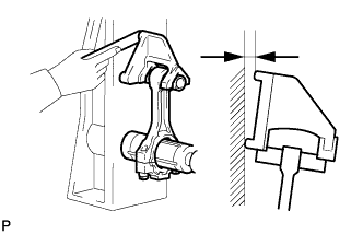
Check for bend.
Maximum bend 0.05 mm (0.0020 in.) per 100 mm (3.937 in.) If the bend is greater than the maximum, replace the connecting rod.
-
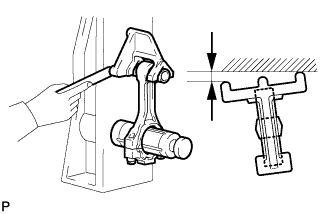
Check for twist.
Maximum twist 0.15 mm (0.0059 in.) per 100 mm (3.937 in.) If the twist is greater than the maximum, replace the connecting rod.
-
-
-
INSPECT CONNECTING ROD BOLT
-
Using a vernier caliper, measure the tension portion diameter of the bolt.
Standard diameter 8.5 to 8.6 mm (0.335 to 0.339 in.) Minimum diameter 8.3 mm (0.327 in.) If the diameter is less than the minimum, replace the bolt.
-
-
INSPECT CRANKSHAFT
-
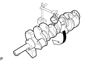
Inspect for circle runout.
-
Place the crankshaft on V-blocks.
-
Using a dial indicator, measure the circle runout at the center journal.
Maximum circle runout 0.06 mm (0.0024 in.) If the circle runout is greater than the maximum, replace the crankshaft.
-
-
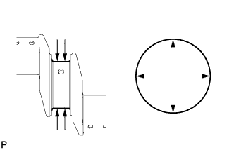
Inspect the main journals.
-
Using a micrometer, measure the diameter of each main journal.
Standard journal diameter 66.988 to 67.000 mm (2.6373 to 2.6378 in.) If the diameter is not as specified, check the oil clearance. If necessary, replace the crankshaft.
-
Check each main journal for taper and out-of-round as shown in the illustration.
Maximum taper and out-of-round 0.02 mm (0.0008 in.) If the taper and out-of-round is greater than the maximum, replace the crankshaft.
-
-
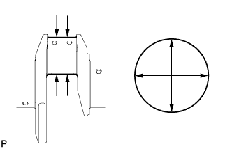
Inspect the crank pin.
-
Using a micrometer, measure the diameter of each crank pin.
Standard crank pin diameter 52.982 to 53.000 mm (2.0859 to 2.0866 in.) If the diameter is not as specified, check the oil clearance. If necessary, replace the crankshaft.
-
Check each crank pin for taper and out-of-round as shown in the illustration.
Maximum taper and out-of-round 0.02 mm (0.0008 in.) If the taper and out-of-round is greater than the maximum, replace the crankshaft.
-
-
-
INSPECT CRANKSHAFT OIL CLEARANCE
-
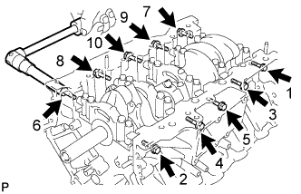
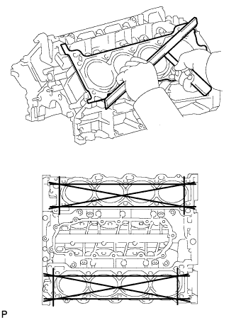
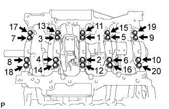
Uniformly loosen and remove the 10 bearing cap bolts and 10 seal washers in several steps, in the sequence shown the illustration.
-
Uniformly loosen the 20 bearing cap bolts in several steps, in the sequence shown in the illustration.
-
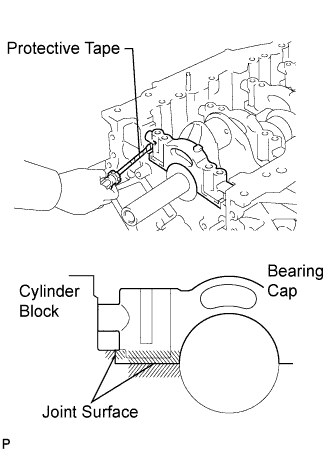
Using a screwdriver, pry out the main bearing caps. Remove the 5 main bearing caps and lower bearings.
Tech Tips
Tape the screwdriver tip before use.
Note
-
Pry up the main cap little by little to the right and left in turns.
-
Be careful not to damage the joint surface of the cylinder block and main bearing caps.
-
-
Clean each main journal and bearing.
-
Check each main journal and bearing for pitting and scratches.
Tech Tips
If the journal or bearing is damaged, replace the bearing.
-
Place the crankshaft on the cylinder block.
-
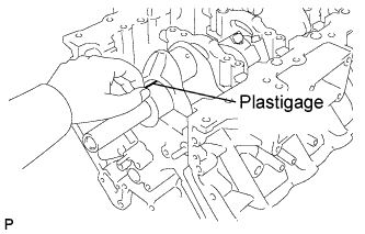
Lay a strip of Plastigage across each journal.
-
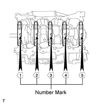
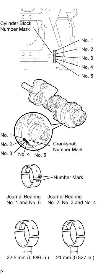
Examine the front marks and numbers, and install the bearing caps on the cylinder block.
Tech Tips
A number is marked on each main bearing cap to indicate the installation position.
-
Apply a light coat of engine oil on the threads and under the heads of the bearing cap bolts.
-
Place the crankshaft bearing cap on the cylinder block.
-
Temporarily install the 10 main bearing cap bolts to the inside positions.
-
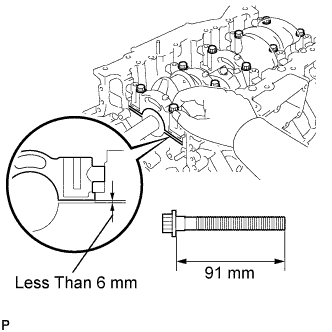
Insert the main bearing cap by hand until the clearance between the main bearing cap and cylinder block is less than 6 mm (0.23 in.) by marking the 2 internal bearing cap bolts as a guide.
Bolt length 91 mm (3.583 in.) -
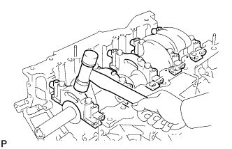
Using a plastic-faced hammer, lightly tap the bearing cap to ensure a proper fit.
-
Apply a light coat of engine oil to the threads and under the heads of the 10 main bearing cap bolts.
-
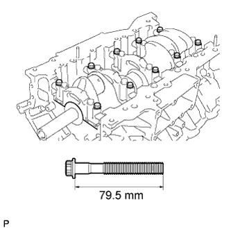
Temporarily install the 10 main bearing cap bolts to the outside positions.
Bolt length 79.5 mm (3.130 in.) Tech Tips
The main bearing cap bolts are tightened in 2 progressive steps.
-
Step 1:
-
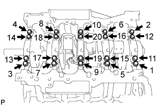
Install and uniformly tighten the 20 main bearing cap bolts in the sequence shown in the illustration.
- Torque:
- for inside position
- 61 N*m { 622 kgf*cm, 45 ft.*lbf }
- for outside position
- 27 N*m { 275 kgf*cm, 20 ft.*lbf }
If any of the main bearing cap bolts does not meet the specified torque, replace it.
Note
Do not turn the crankshaft.
-
-
Step 2:
-
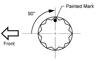
Mark the front of the bearing cap bolts with paint.
-
Tighten the bearing cap bolts another 90° in the order shown in step 1.
-
Check that the painted marks are now at a 90° angle to the front.
-
-
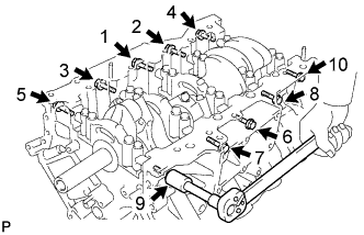
Install and uniformly tighten the 10 main bearing cap bolts and 10 seal washers in several steps, in the sequence shown in the illustration.
- Torque:
- 45 N*m { 459 kgf*cm, 33 ft.*lbf }
-
Remove the 30 bolts and bearing caps.
-
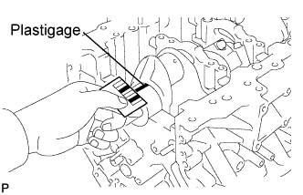
Measure the plastigage at its widest point.
Standard oil clearance Number Mark Specified Condition No. 1 and No. 5 journal 0.017 to 0.030 mm (0.0007 to 0.0012 in.) Other journal 0.024 to 0.037 mm (0.0009 to 0.0015 in.) Maximum oil clearance Number Mark Specified Condition No. 1 and No. 5 journal 0.050 mm (0.0020 in.) Other journal 0.060 mm (0.0024 in.) If the oil clearance is greater than the maximum, replace the bearings. If necessary, replace the crankshaft.
Tech Tips
If replacing a bearing, replace it with one having the same number. If the number of the bearing cannot be determined, select the correct bearing by adding together the numbers imprinted on the cylinder block and crankshaft. Refer to the table below for the appropriate bearing number. There are 6 sizes of standard bearings. For No. 1 and No. 5 position bearings, use bearings marked 4, 5, 6, 7, 8 and 9. For other position bearings, use bearing marked 3, 4, 5, 6, 7 and 8.
-
Example:
Cylinder block "07" + Crankshaft "06" = Total number 13 (Use upper bearing "6" and lower bearing "7")
Standard crankshaft main journal diameter Number Mark Specified Condition 00 66.999 to 67.000 mm (2.63776 to 2.63780 in.) 01 66.998 to 66.999 mm (2.63772 to 2.63776 in.) 02 66.997 to 66.998 mm (2.63768 to 2.63772 in.) 03 66.996 to 66.997 mm (2.63764 to 2.63768 in.) 04 66.995 to 66.996 mm (2.63760 to 2.63764 in.) 05 66.994 to 66.995 mm (2.63756 to 2.63760 in.) 06 66.993 to 66.994 mm (2.63752 to 2.63756 in.) 07 66.992 to 66.993 mm (2.63748 to 2.63752 in.) 08 66.991 to 66.992 mm (2.63744 to 2.63748 in.) 09 66.990 to 66.991 mm (2.63740 to 2.63744 in.) 10 66.989 to 66.990 mm (2.63736 to 2.63740 in.) 11 66.988 to 66.989 mm (2.63736 to 2.63736 in.) Standard bearing center wall thickness No. 1 and No. 5 journal (A) + (B) Upper bearing Lower bearing Number Mark Specified condition Number Mark Specified condition 00 to 02 4 2.501 to 2.504 mm (0.0985 to 0.0986 in.) 5 2.488 to 2.491 mm (0.0980 to 0.0981 in.) 03 to 05 5 2.504 to 2.507 mm (0.0986 to 0.0987 in.) 5 2.488 to 2.491 mm (0.0980 to 0.0981 in.) 06 to 08 5 2.504 to 2.507 mm (0.0986 to 0.0987 in.) 6 2.491 to 2.494 mm (0.0981 to 0.0982 in.) 09 to 11 6 2.507 to 2.510 mm (0.0987 to 0.0988 in.) 6 2.491 to 2.494 mm (0.0981 to 0.0982 in.) 12 to 14 6 2.507 to 2.510 mm (0.0987 to 0.0988 in.) 7 2.494 to 2.497 mm (0.0982 to 0.0983 in.) 15 to 17 7 2.510 to 2.513 mm (0.0988 to 0.0989 in.) 7 2.494 to 2.497 mm (0.0982 to 0.0983 in.) 18 to 20 7 2.510 to 2.513 mm (0.0988 to 0.0989 in.) 8 2.497 to 2.500 mm (0.0983 to 0.0984 in.) 21 to 23 8 2.513 to 2.516 mm (0.0989 to 0.0991 in.) 8 2.497 to 2.500 mm (0.0983 to 0.0984 in.) 24 to 26 8 2.513 to 2.516 mm (0.0989 to 0.0991 in.) 9 2.500 to 2.503 mm (0.0984 to 0.0985 in.) 27 to 28 9 2.516 to 2.519 mm (0.0991 to 0.0992 in.) 9 2.500 to 2.503 mm (0.0984 to 0.0985 in.) Standard bearing center wall thickness other journal (A) + (B) Upper bearing Lower bearing Number Mark Specified condition Number Mark Specified condition 00 to 02 3 2.482 to 2.485 mm (0.0977 to 0.0978 in.) 4 2.501 to 2.504 mm (0.0985 to 0.0986 in.) 03 to 05 4 2.485 to 2.488 mm (0.0978 to 0.0980 in.) 4 2.501 to 2.504 mm (0.0985 to 0.0986 in.) 06 to 08 4 2.485 to 2.488 mm (0.0978 to 0.0980 in.) 5 2.504 to 2.507 mm (0.0986 to 0.0987 in.) 09 to 11 5 2.488 to 2.491 mm (0.0980 to 0.0981 in.) 5 2.504 to 2.507 mm (0.0986 to 0.0987 in.) 12 to 14 5 2.488 to 2.491 mm (0.0980 to 0.0981 in.) 6 2.507 to 2.510 mm (0.0987 to 0.0988 in.) 15 to 17 6 2.491 to 2.494 mm (0.0981 to 0.0982 in.) 6 2.507 to 2.510 mm (0.0987 to 0.0988 in.) 18 to 20 6 2.491 to 2.494 mm (0.0981 to 0.0982 in.) 7 2.510 to 2.513 mm (0.0988 to 0.0989 in.) 21 to 23 7 2.494 to 2.497 mm (0.0982 to 0.0983 in.) 7 2.510 to 2.513 mm (0.0988 to 0.0989 in.) 24 to 26 7 2.494 to 2.497 mm (0.0982 to 0.0983 in.) 8 2.513 to 2.516 mm (0.0989 to 0.0991 in.) 27 to 28 8 2.497 to 2.500 mm (0.0983 to 0.0984 in.) 8 2.513 to 2.516 mm (0.0989 to 0.0991 in.) -
-
Completely remove the Plastigage.
-
-
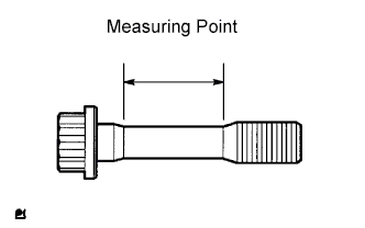
INSPECT CRANKSHAFT BEARING CAP SET BOLT
-
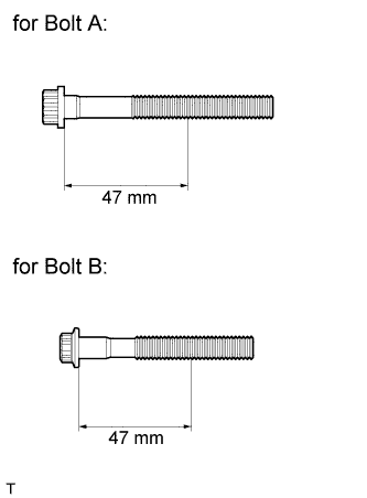
Using a vernier caliper, measure the minimum diameter of the elongated thread at the measuring point.
Standard diameter 10.8 to 11.0 mm (0.425 to 0.433 in.) for bolt A 9.8 to 10.0 mm (0.386 to 0.394 in.) for bolt B Minimum diameter 10.7 mm (0.421 in.) for bolt A 9.7 mm (0.382 in.) for bolt B Measuring point 47 mm (1.850 in.) If the diameter is less than the minimum, replace the bolt.
-