TIMING CHAIN INSTALLATION

-
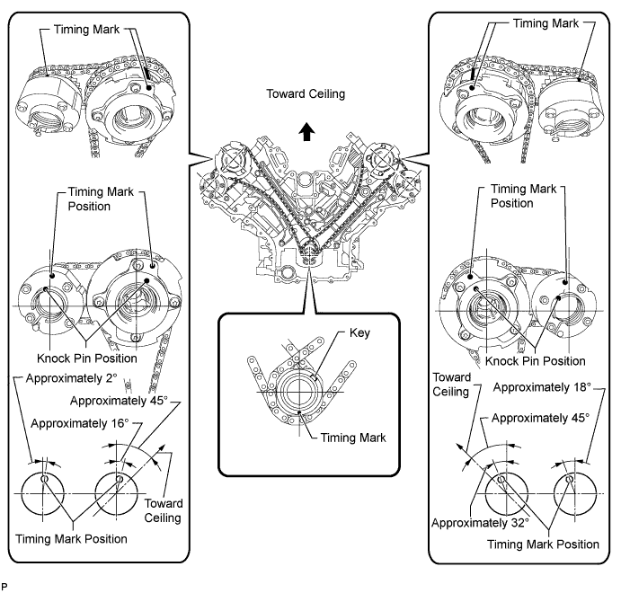
SET NO. 1 CYLINDER TO TDC / COMPRESSION
-
Temporarily install the crankshaft pulley bolt.
-
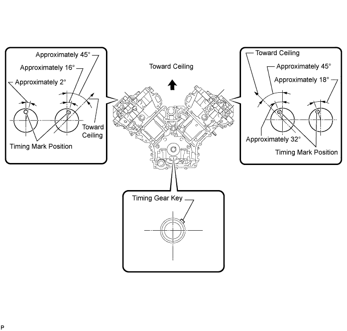
Rotate the crankshaft so that the timing gear key is as shown in the illustration. Then, using a wrench, rotate each camshaft so that the timing marks are as shown in the illustration.
Note
When the crankshaft or a camshaft is rotated excessively, the valves and pistons may interfere with each other.
-
Remove the crankshaft pulley bolt.
-
-
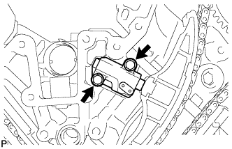
INSTALL NO. 2 CHAIN TENSIONER ASSEMBLY
-
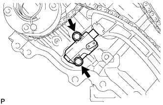
Install the chain tensioner with the 2 bolts.
- Torque:
- 10 N*m { 102 kgf*cm, 7 ft.*lbf }
-
While raising up the No. 2 chain tensioner, insert a pin with a diameter 1.0 mm (0.039 in.) into the hole to fix it in place.
-
-
SET CAMSHAFT TIMING GEAR ASSEMBLY (for Bank 2)
-
Check the camshaft timing gear position.
Tech Tips
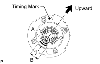
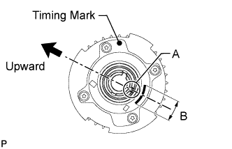
When reusing the camshaft timing gear, make sure that the groove labeled A is positioned within the mark labeled B. If the groove is not positioned within the mark, perform the following procedures to align the groove with the mark.
-
Set the camshaft timing gear position.
-
Turn the camshaft timing gear's eccentric shaft keyway part counterclockwise by hand and set it to the maximum retard angle.
Tech Tips
The position where the eccentric shaft stops is the maximum retard angle.
Note
When turning the eccentric shaft keyway part, do not use any tools as the keyway part may be damaged.
-
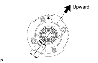
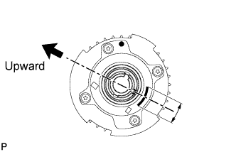
Turn the eccentric shaft clockwise until the groove labeled A and mark labeled B are aligned as shown in the illustration.
Tech Tips
-
Make sure that the groove labeled A is positioned as close as possible to the center of the mark labeled B.
-
When installing the engine, make sure that the groove labeled A and mark labeled B are facing upward with respect to the ground as indicated by the arrow in the illustration.
-
-
-
-
INSTALL CHAIN SUB-ASSEMBLY (for Bank 2)
-
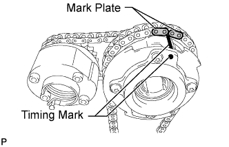
Align the No. 1 chain's orange mark plates with the camshaft timing gear's timing mark and install the chain to the gear as shown in the illustration.
-
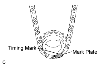
Align the No. 1 chain's orange mark plate with the crankshaft timing gear's timing mark and install the chain to the gear as shown in the illustration.
-
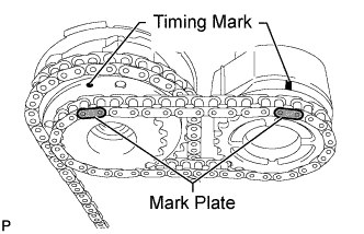
Align the No. 2 chain's mark plates (yellow) with the timing marks (1-dot mark) of the camshaft timing gear assembly and camshaft timing exhaust gear assembly and install the No. 2 chain to the gears as shown in the illustration.
Tech Tips
The crankshaft timing gear and camshaft exhaust gear assembly will be installed with the No. 1 and No. 2 chains connected to the gears.
-
Install the crankshaft timing gear to the crankshaft.
-
Align and attach the knock pin of the No. 1 camshaft with the pin hole of the camshaft timing gear assembly.
Tech Tips
Make sure that the arrow is facing upward with respect to the ground.
-
Using the hexagonal portion of the No. 2 camshaft, align and attach the knock pin of the No. 2 camshaft with the pin hole of the camshaft timing exhaust gear assembly.
-
Remove the pin from the No. 2 chain tensioner.
-
-
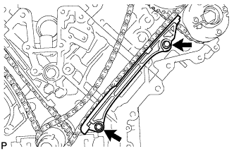
INSTALL NO. 1 CHAIN VIBRATION DAMPER (for Bank 2)
-
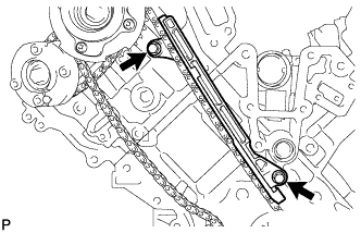
Install the vibration damper with the 2 bolts.
- Torque:
- 21 N*m { 214 kgf*cm, 15 ft.*lbf }
-
-
INSTALL CHAIN TENSIONER SLIPPER (for Bank 2)
Tech Tips
If you cannot install the chain tensioner slipper due to the tension of the chain, use the hexagonal portion of the camshaft to loosen the chain, and then install the chain tensioner slipper.
-
INSTALL NO. 1 CHAIN TENSIONER ASSEMBLY (for Bank 2)
-
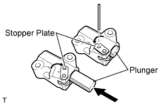
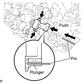
Move the stopper plate upward to release the lock and push the plunger deep into the tensioner.
-
Move the stopper plate downward to set the lock and insert a hexagon wrench into the hole of the stopper plate.
-
Install the chain tensioner with the 2 bolts.
- Torque:
- 10 N*m { 102 kgf*cm, 7 ft.*lbf }
-
Remove the hexagon wrench from the chain tensioner.
-
-
INSTALL NO. 3 CHAIN TENSIONER ASSEMBLY
-
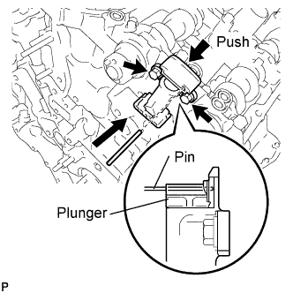
Install the chain tensioner with the 2 bolts.
- Torque:
- 10 N*m { 102 kgf*cm, 7 ft.*lbf }
-
While pushing down the No. 3 chain tensioner, insert a pin with a diameter of 1.0 mm (0.039 in.) into the hole to fix it in place.
-
-
SET CAMSHAFT TIMING GEAR ASSEMBLY LH (for Bank 1)
-
Check the camshaft timing gear position.
Tech Tips
When reusing the camshaft timing gear, make sure that the groove labeled A is positioned within the mark labeled B. If the groove is not positioned within the mark, perform the following procedures to align the groove with the mark.
-
Set the camshaft timing gear position.
-
Turn the camshaft timing gear's eccentric shaft keyway part counterclockwise by hand and set it to the maximum retard angle.
Tech Tips
The position where the eccentric shaft stops is the maximum retard angle.
Note
When turning the eccentric shaft keyway part, do not use any tools as the keyway part may be damaged.
-
Turn the eccentric shaft clockwise until the groove labeled A and mark labeled B are aligned as shown in the illustration.
Tech Tips
-
Make sure that the groove labeled A is positioned as close as possible to the center of the mark labeled B.
-
When installing the engine, make sure that the groove labeled A and mark labeled B are facing upward with respect to the ground as indicated by the arrow in the illustration.
-
-
-
-
INSTALL CHAIN SUB-ASSEMBLY (for Bank 1)
-
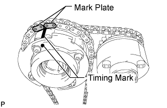
Align the No. 1 chain's orange mark plates with the camshaft timing gear's timing mark and install the chain to the gear as shown in the illustration.
-
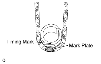
Align the No. 1 chain's orange mark plate with the crankshaft timing gear's timing mark and install the chain to the gear as shown in the illustration.
-
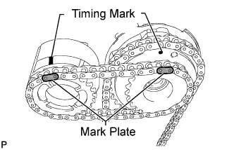
Align the No. 2 chain's mark plates (yellow) with the timing marks (1-dot mark) of the camshaft timing gear assembly and camshaft timing exhaust gear assembly and install the No. 2 chain to the gears as shown in the illustration.
Tech Tips
The crankshaft timing gear and camshaft exhaust gear assembly will be installed with the No. 1 and No. 2 chains connected to the gears.
-
Install the crankshaft timing gear to the crankshaft.
-
Align and attach the knock pin of the No. 3 camshaft with the pin hole of the camshaft timing gear assembly.
Tech Tips
Make sure that the arrow is facing upward with respect to the ground.
-
Using the hexagonal portion of the No. 4 camshaft, align and attach the knock pin of the No. 4 camshaft with the pin hole of the camshaft timing exhaust gear assembly.
Note
Because the gears' timing mark positions may shift due to looseness of the No. 1 chain, use the hexagonal portion of the camshaft to hold the No. 3 camshaft in place until the No. 1 chain tensioner is installed.
-
Remove the pin from the No. 2 chain tensioner.
-
-
INSTALL CHAIN TENSIONER SLIPPER (for Bank 1)
Tech Tips
If you cannot install the chain tensioner slipper due to the tension of the chain, use the hexagonal portion of the camshaft to loosen the chain, and then install the chain tensioner.
-
INSTALL NO. 1 CHAIN TENSIONER ASSEMBLY (for Bank 1)
-
Move the stopper plate upward to release the lock and push the plunger deep into the tensioner.
-
Move the stopper plate downward to set the lock and insert a hexagon wrench into the hole of the stopper plate.
-
Install the chain tensioner and a new gasket with the 2 bolts.
- Torque:
- 10 N*m { 102 kgf*cm, 7 ft.*lbf }
-
-
INSTALL NO. 1 CHAIN VIBRATION DAMPER (for Bank 1)
-
Install the vibration damper with the 2 bolts.
- Torque:
- 21 N*m { 214 kgf*cm, 15 ft.*lbf }
-
Remove the hexagon wrench from the No. 1 chain tensioner.
-
-
TIGHTEN CAMSHAFT TIMING GEAR ASSEMBLY
-
for Bank 1:
-
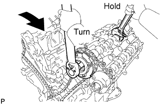
Using a wrench, hold the hexagonal portion of the No. 3 camshaft.
-
Using a 12 mm socket hexagon wrench, tighten the camshaft timing gear assembly with a new bolt.
- Torque:
- 79 N*m { 806 kgf*cm, 58 ft.*lbf }
-
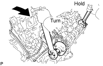
Using a wrench to hold the hexagonal portion of the No. 4 camshaft, tighten the camshaft timing exhaust gear assembly with the bolt.
- Torque:
- 100 N*m { 1020 kgf*cm, 74 ft.*lbf }
-
-
for Bank 2:
-
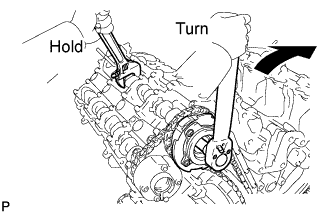
Using a wrench, hold the hexagonal portion of the No. 1 camshaft.
-
Using a 12 mm socket hexagon wrench, tighten the camshaft timing gear assembly with a new bolt.
- Torque:
- 79 N*m { 806 kgf*cm, 58 ft.*lbf }
-
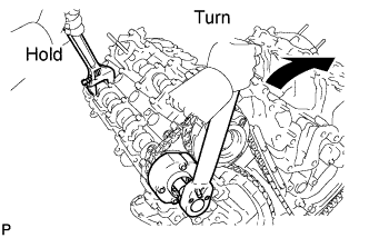
Using a wrench to hold the hexagonal portion of the No. 2 camshaft, tighten the camshaft timing exhaust gear assembly with the bolt.
- Torque:
- 100 N*m { 1020 kgf*cm, 74 ft.*lbf }
-
-
-
CHECK NO. 1 CYLINDER TO TDC / COMPRESSION
-
Temporarily install the crankshaft pulley bolt.
-
Rotate the crankshaft clockwise and check that the timing marks on the crankshaft timing gear and camshaft timing gears are as shown in the illustration.
-
Remove the crankshaft pulley bolt.
-
-
INSTALL TIMING CHAIN COVER SUB-ASSEMBLY
-
for 2WD: Click here
-
for AWD: Click here
-