ENGINE UNIT REASSEMBLY

-
INSTALL OIL PAN STUD BOLT
Note
If a stud bolt is deformed or the threads are damaged, replace it.
-
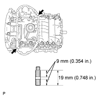
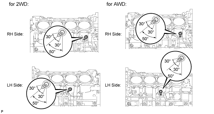
for 2WD:
Using an E6 "TORX" socket wrench, install the 2 stud bolts as shown in the illustration.
- Torque:
- 5.0 N*m { 51 kgf*cm, 44 in.*lbf }
-
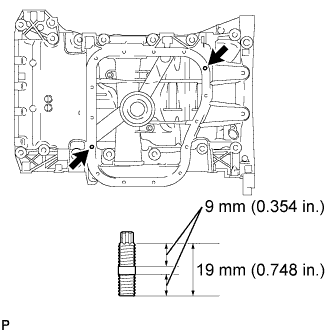
for AWD:
Using an E6 "TORX" socket wrench, install the 2 stud bolts as shown in the illustration.
- Torque:
- 5.0 N*m { 51 kgf*cm, 44 in.*lbf }
-
-
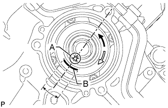
INSTALL NO. 1 VENTILATION CONNECTOR
-
Install the No. 1 ventilation connector as shown in the illustration.
Acceptable angle (A) -5 to 5° Tap-in depth (B) 0.2 to 3.2 mm (0.008 to 0.126 in.) Note
After the installation of the ventilation connector, do not rotate it.
Tech Tips
Connect the No. 1 ventilation connector so that its flat surface faces the rear part of the engine.
-
-
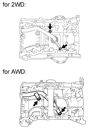
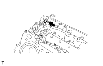
INSTALL OIL DRAIN PIPE SUB-ASSEMBLY
-
Apply a light coat of engine oil to a new O-ring.
-
Install the new O-ring to the drain pipe.
-
Install the oil drain pipe with the bolt.
- Torque:
- 10 N*m { 102 kgf*cm, 7 ft.*lbf }
-
-
INSTALL ENGINE REAR OIL SEAL RETAINER
-
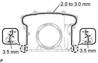
Apply seal packing in a continuous line as shown in the illustration.
Seal packing Toyota Genuine Seal Packing Black, Three Bond 1207B or equivalent Seal diameter 2.0 to 3.0 mm (0.079 to 0.118 in.) Application position from inside edge of retainer 3.5 mm (0.138 in.) Note
-
Remove any oil from the contact surface.
-
Install the oil pan within 3 minutes and tighten the bolts and nuts within 15 minutes after applying seal packing.
-
Do not start the engine for at least 2 hours after installing.
-
When installing the oil seal retainer, make sure the lip of the oil seal is not damaged.
-
When installing the oil seal retainer, make sure the lip of the oil seal is not folded incorrectly.
-
-
Install the oil seal retainer with the 6 bolts.
- Torque:
- 10 N*m { 102 kgf*cm, 7 ft.*lbf }
-
-
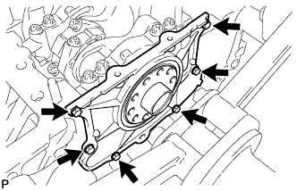
INSTALL OIL STRAINER SUB-ASSEMBLY
-
Apply a light coat of engine oil to a new O-ring.
-
Install the new O-ring to the oil strainer.
-
Install the oil strainer with the 2 bolts.
- Torque:
- 21 N*m { 214 kgf*cm, 15 ft.*lbf }
Note
Make sure the O-ring is not twisted or damaged.
-
-
INSTALL NO. 2 OIL PAN BAFFLE PLATE (for AWD)
-
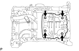
Install the baffle plate with the 4 bolts.
- Torque:
- 10 N*m { 102 kgf*cm, 7 ft.*lbf }
-
-
INSTALL NO. 1 OIL PAN BAFFLE PLATE
-
for 2WD:
Install the baffle plate with the 8 bolts.
- Torque:
- 10 N*m { 102 kgf*cm, 7 ft.*lbf }
-
for AWD:
Install the baffle plate with the 4 bolts.
- Torque:
- 10 N*m { 102 kgf*cm, 7 ft.*lbf }
-
-
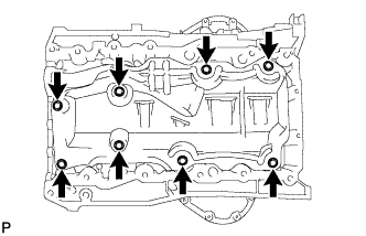
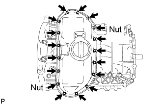
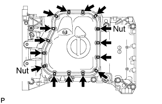
INSTALL OIL PAN SUB-ASSEMBLY
-
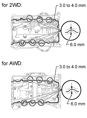
Apply seal packing in a continuous line as shown in the illustration.
Seal packing Toyota Genuine Seal Packing Black, Three Bond 1207B or equivalent Standard seal diameter 3.0 to 4.0 mm (0.118 to 0.156 in.) Application position from inside edge of oil pan 6.0 mm (0.236 in.) Note
-
Remove any oil from the contact surface.
-
Install the oil pan within 3 minutes and tighten the bolts and nuts within 15 minutes after applying seal packing.
-
-
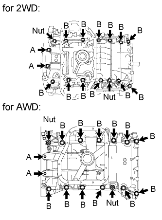
Install the oil pan with the 14 bolts and 2 nuts.
- Torque:
- for bolt A
- 10 N*m { 102 kgf*cm, 7 ft.*lbf }
- for bolt B and nut
- 35 N*m { 357 kgf*cm, 26 ft.*lbf }
Note
Do not start the engine for at least 2 hours after installing.
-
-
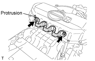
INSTALL OIL PAN PROTECTOR (for 2WD)
-
Install the protector with the 2 nuts.
- Torque:
- 5.0 N*m { 51 kgf*cm, 44 in.*lbf }
Tech Tips
Install the oil pan protector with its protrusion facing the bottom of the engine.
-
-
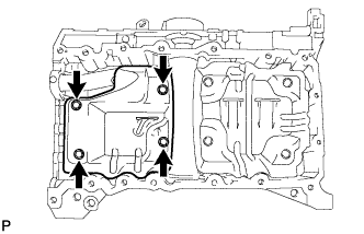
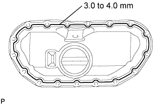
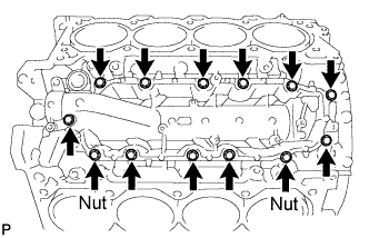
INSTALL NO. 2 OIL PAN SUB-ASSEMBLY
-
for 2WD:
-
Apply seal packing in a continuous line as shown in the illustration.
Seal packing Toyota Genuine Seal Packing Black, Three Bond 1207B or equivalent Standard seal diameter 3.0 to 4.0 mm (0.118 to 0.156 in.) Note
-
Remove any oil from the contact surface.
-
Install the oil pan within 3 minutes and tighten the bolts and nuts within 10 minutes after applying seal packing.
-
Do not start the engine for at least 2 hours after installing.
-
-
Install the oil pan with the 15 bolts and 2 nuts.
- Torque:
- 10 N*m { 102 kgf*cm, 7 ft.*lbf }
-
-
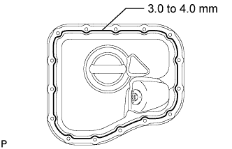
for AWD:
-
Apply seal packing in a continuous line as shown in the illustration.
Seal packing Toyota Genuine Seal Packing Black, Three Bond 1207B or equivalent Standard seal diameter 3.0 to 4.0 mm (0.118 to 0.157 in.) Note
-
Remove any oil from the contact surface.
-
Install the oil pan within 3 minutes and tighten the bolts and nuts within 10 minutes after applying seal packing.
-
-
Install the oil pan with the 13 bolts and 2 nuts.
- Torque:
- 10 N*m { 102 kgf*cm, 7 ft.*lbf }
Note
Do not start the engine for at least 2 hours after installing.
-
-
-
INSTALL VENTILATION PIPE GASKET
-
Using SST, evenly tap in a new ventilation pipe gasket until its surface is flush with the lip of the ventilation pipe.
- SST
- 09950-60010 ( 09951-00360 )
- 09950-70010 ( 09951-07100 )
Tech Tips
-
Do not tap the gasket at an angle.
-
Do not tap the gasket excessively.
-
-
INSTALL NO. 1 HEAT EXCHANGER COVER
-

Apply seal packing in a continuous line as shown in the illustration.
Seal packing Toyota Genuine Seal Packing 1282B, Three Bond 1282B or equivalent Standard seal diameter 3.0 to 4.0 mm (0.118 to 0.157 in.) Note
-
Remove any oil from the contact surface.
-
Install the heat exchanger cover within 3 minutes and tighten the bolts and nuts within 15 minutes after applying seal packing.
-
-
Install the heat exchanger cover with the 11 bolts and 2 nuts.
- Torque:
- 21 N*m { 214 kgf*cm, 15 ft.*lbf }
Note
Do not start the engine for at least 2 hours after installing.
-
Install the bolt.
- Torque:
- 10 N*m { 102 kgf*cm, 7 ft.*lbf }
-
-
INSTALL OIL RETURN PIPE GASKET
-
Install a new oil return pipe gasket.
-
-
INSTALL CYLINDER BLOCK WATER JACKET SPACER
-
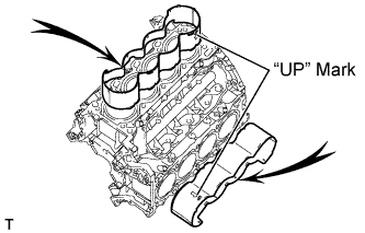
Install the 2 water jacket spacers as shown in the illustration.
Tech Tips
-
Face the cutouts (indicated by arrows in illustration) away from the engine.
-
Face the "up mark" as shown in the illustration.
-
-
-
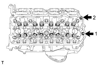
INSTALL CYLINDER HEAD SUB-ASSEMBLY (for Bank 1)
-
Check the piston protrusions for each cylinder.
-
Clean the cylinder block with solvent.
-
Set the piston of the cylinder to be measured to slightly ATDC.
-
-
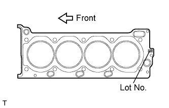
Place the cylinder head gasket on the cylinder block surface with the front face of the Lot No. stamp upward.
Note
-
Be careful of the installation direction.
-
Gently place the cylinder head in order not to damage the gasket with the bottom part of the head.
-
-
Place the cylinder head on the cylinder block.
Note
Ensure that no oil is on the mounting surface of the cylinder head.
Tech Tips
The cylinder head bolts are tightened in 3 progressive steps.
-
Apply a light coat of engine oil to the threads and under the heads of the cylinder head bolts.
-
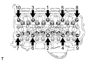
Step 1:
-
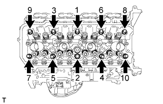
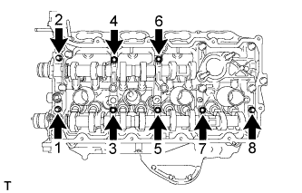
Using a 10 mm bi-hexagon wrench, install and uniformly tighten the 10 cylinder head bolts with the plate washers in several steps, in the sequence shown in the illustration.
- Torque:
- 36 N*m { 367 kgf*cm, 27 ft.*lbf }
-
-
Step 2:
-
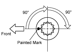
Mark the cylinder head bolt head with paint as shown in the illustration.
-
Tighten the cylinder head bolts another 90° in the sequence shown in step 1.
-
-
Step 3:
-
Tighten the cylinder head bolts by an additional 90° in the sequence shown in step 1.
-
Check that the painted marks are now facing rearward.
-
-
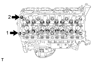
Uniformly install the 2 bolts in the sequence shown in the illustration.
- Torque:
- 21 N*m { 214 kgf*cm, 15 ft.*lbf }
-
-
INSTALL CYLINDER HEAD SUB-ASSEMBLY (for Bank 2)
-
Check the piston protrusions for each cylinder.
-
Clean the cylinder block with solvent.
-
Set the piston of the cylinder to be measured to slightly ATDC.
-
-
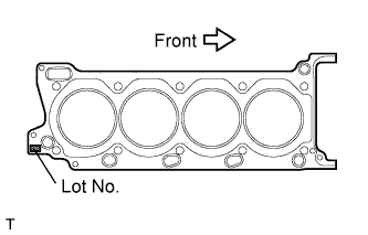
Place the cylinder head gasket on the cylinder block surface with the front face of the Lot No. stamp upward.
Note
-
Be careful of the installation direction.
-
Gently place the cylinder head in order not to damage the gasket with the bottom part of the head.
-
-
Place the cylinder head on the cylinder block.
Note
Ensure that no oil is on the mounting surface of the cylinder head.
Tech Tips
The cylinder head bolts are tightened in 3 progressive steps.
-
Apply a light coat of engine oil to the threads and under the heads of the cylinder head bolts.
-
Step 1:
-
Using a 10 mm bi-hexagon wrench, install and uniformly tighten the 10 cylinder head bolts with the plate washers in several steps, in the sequence shown in the illustration.
- Torque:
- 36 N*m { 367 kgf*cm, 27 ft.*lbf }
-
-
Step 2:
-
Mark the cylinder head bolt head with paint as shown in the illustration.
-
Tighten the cylinder head bolts another 90° in the sequence shown in step 1.
-
-
Step 3:
-
Tighten the cylinder head bolts by an additional 90° in the sequence shown in step 1.
-
Check that the painting marks are now facing rearward.
-
-
Uniformly install the 2 bolts in the sequence shown in the illustration.
- Torque:
- 21 N*m { 214 kgf*cm, 15 ft.*lbf }
-
-
INSTALL VALVE STEM CAP
-
Apply a light coat of engine oil to the valve stem caps.
-
Install the 32 valve stem caps to the cylinder head.
-
-
INSTALL VALVE LASH ADJUSTER ASSEMBLY
-
Be sure to inspect the valve lash adjuster before installing it Click here.
-
Install the 32 valve lash adjusters to the cylinder head.
Note
Install the lash adjuster at the same place it was removed from.
-
-
INSTALL NO. 1 VALVE ROCKER ARM SUB-ASSEMBLY
-
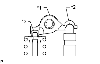
Text in Illustration *1 No. 1 Valve Rocker Arm Sub-assembly *2 Valve Lash Adjuster Assembly *3 Valve Stem Cap Apply engine oil to the lash adjuster tips and valve stem cap ends.
-
Make sure that the 32 valve rocker arms are installed as shown in the illustration.
-
-
INSTALL CAMSHAFT BEARING CAP (for Bank 2)
-
Apply a light coat of engine oil to the camshaft journals, camshaft housings and bearing caps.
-
Install the No. 1 and No. 2 camshaft to the camshaft housing.
-
Confirm the marks and numbers on the camshaft bearing caps and place them each in their proper positions and directions.
-
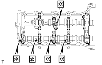
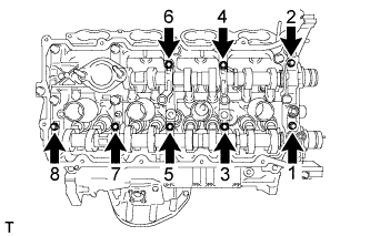
Temporarily install the 8 bolts in the order shown in the illustration.
-
-
INSTALL CAMSHAFT HOUSING SUB-ASSEMBLY (for Bank 2)
-
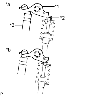
Text in Illustration *1 No. 1 Valve Rocker Arm Sub-assembly *2 Valve Stem Cap *3 Valve Lash Adjuster Assembly *a INCORRECT *b CORRECT Make sure that the valve rocker arms are installed as shown in the illustration.
-
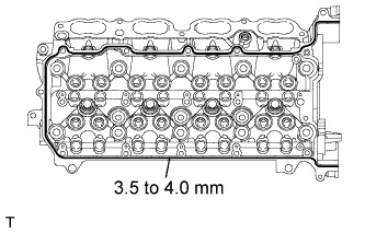
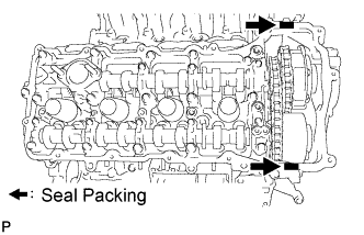
Apply seal packing in a continuous line as shown in the illustration.
Seal packing Toyota Genuine Seal Packing Black, Three Bond 1207B or equivalent Standard seal diameter 3.5 to 4.0 mm (0.138 to 0.158 in.) Note
-
Remove any oil from the contact surface.
-
Install the camshaft housing within 3 minutes and tighten the bolts within 15 minutes after applying seal packing.
-
Do not start the engine for at least 2 hours after the installation.
-
-
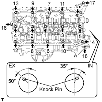
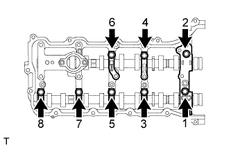
Install the camshaft housing, and install the 18 bolts in the order shown in the illustration.
- Torque:
- for bolt A
- 10 N*m { 102 kgf*cm, 7 ft.*lbf }
- except bolt A
- 30 N*m { 306 kgf*cm, 22 ft.*lbf }
Note
Make sure that the knock pin of the camshaft is positioned as shown in the illustration before installing the camshaft housing.
-
Tighten the 8 bolts in the order shown in the illustration.
- Torque:
- 16 N*m { 163 kgf*cm, 12 ft.*lbf }
Note
Thoroughly wipe clean any seal packing.
-
-
INSTALL CAMSHAFT BEARING CAP (for Bank 1)
-
Apply a light coat of engine oil to the camshaft journals, camshaft housings and bearing caps.
-
Install the No. 3 and No. 4 camshaft to the camshaft housing.
-
Confirm the marks and numbers on the camshaft bearing caps and place them each in their proper positions and directions.
-
Temporarily install the 8 bolts in the order shown in the illustration.
-
-
INSTALL CAMSHAFT HOUSING SUB-ASSEMBLY (for Bank 1)
-
Text in Illustration *1 No. 1 Valve Rocker Arm Sub-assembly *2 Valve Stem Cap *3 Valve Lash Adjuster Assembly *a INCORRECT *b CORRECT Make sure that the valve rocker arms are installed as shown in the illustration.
-
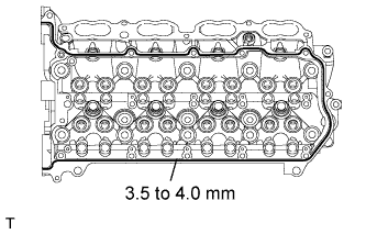
Apply seal packing in a continuous line as shown in the illustration.
Seal packing Toyota Genuine Seal Packing Black, Three Bond 1207B or equivalent Standard seal diameter 3.5 to 4.0 mm (0.138 to 0.158 in.) Note
-
Remove any oil from the contact surface.
-
Install the camshaft housing within 3 minutes and tighten the bolts within 15 minutes after applying seal packing.
-
Do not start the engine for at least 2 hours after the installation.
-
-
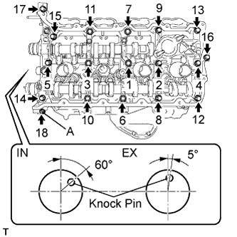
Install the camshaft housing, and install the 18 bolts in the order shown in the illustration.
- Torque:
- for bolt A
- 10 N*m { 102 kgf*cm, 7 ft.*lbf }
- except bolt A
- 30 N*m { 306 kgf*cm, 22 ft.*lbf }
Note
Make sure that the knock pin of the camshaft is positioned as shown in the illustration before installing the camshaft housing.
-
Tighten the 8 bolts in the order shown in the illustration.
- Torque:
- 16 N*m { 163 kgf*cm, 12 ft.*lbf }
Note
Thoroughly wipe clean any seal packing.
-
-
INSTALL CRANKSHAFT TIMING GEAR KEY
-
Install the 2 timing gear keys.
-
-
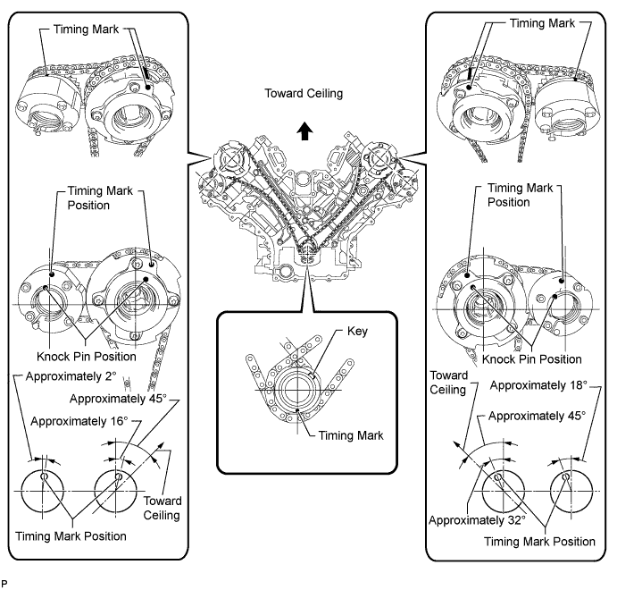
SET NO. 1 CYLINDER TO TDC / COMPRESSION
-
Temporarily install the crankshaft pulley bolt.
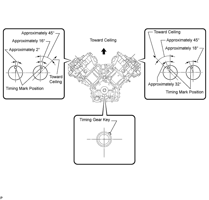
-
Rotate the crankshaft so that the timing gear key is as shown in the illustration. Then, using a wrench, rotate each camshaft so that the timing marks are as shown in the illustration.
Note
When the crankshaft or a camshaft is rotated excessively, the valves and pistons may interfere with each other.
-
Remove the crankshaft pulley bolt.
-
-
INSTALL NO. 2 CHAIN TENSIONER ASSEMBLY
-
Install the chain tensioner with the 2 bolts.
- Torque:
- 10 N*m { 102 kgf*cm, 7 ft.*lbf }
-
While raising up the No. 2 chain tensioner, insert a pin with a diameter 1.0 mm (0.039 in.) into the hole to fix it in place.
-
-
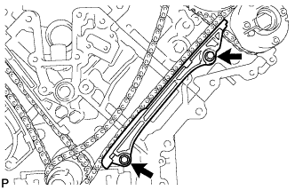
INSTALL CHAIN SUB-ASSEMBLY (for Bank 2)
-
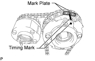
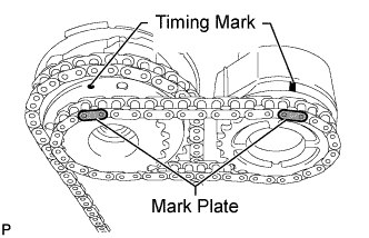
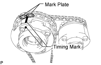
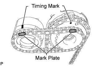
Align the No. 1 chain's orange mark plates with the camshaft timing gear's timing mark and install the chain to the gear as shown in the illustration.
-
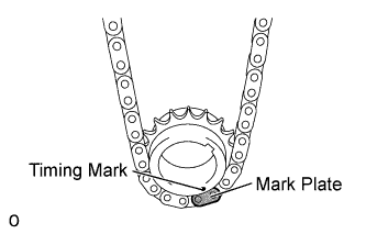
Align the No. 1 chain's orange mark plate with the crankshaft timing gear's timing mark and install the chain to the gear as shown in the illustration.
-
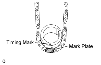
Align the No. 2 chain's mark plates (yellow) with the timing marks (1-dot mark) of the camshaft timing gear assembly and camshaft timing exhaust gear assembly and install the No. 2 chain to the gears as shown in the illustration.
Tech Tips
The crankshaft timing gear and camshaft exhaust gear assembly will be installed with the No. 1 and No. 2 chains connected to the gears.
-
Install the crankshaft timing gear to the crankshaft.
-
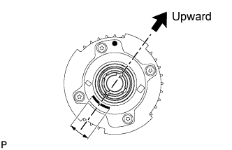
Align and attach the knock pin of the No. 1 camshaft with the pin hole of the camshaft timing gear assembly.
Tech Tips
Make sure that the arrow is facing upward with respect to the ground.
-
Using the hexagonal portion of the No. 2 camshaft, align and attach the knock pin of the No. 2 camshaft with the pin hole of the camshaft timing exhaust gear assembly.
-
Remove the pin from the No. 2 chain tensioner.
-
-
INSTALL NO. 1 CHAIN VIBRATION DAMPER (for Bank 2)
-
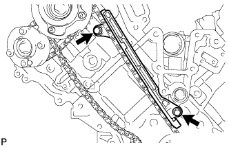
Install the vibration damper with the 2 bolts.
- Torque:
- 21 N*m { 214 kgf*cm, 15 ft.*lbf }
-
-
INSTALL CHAIN TENSIONER SLIPPER (for Bank 2)
Tech Tips
If you cannot install the chain tensioner slipper due to the tension of the chain, use the hexagonal portion of the camshaft to loosen the chain, and then install the chain tensioner slipper.
-
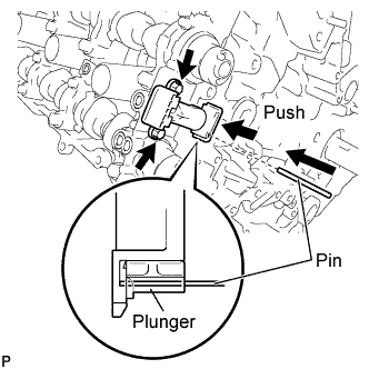
INSTALL NO. 1 CHAIN TENSIONER ASSEMBLY (for Bank 2)
-
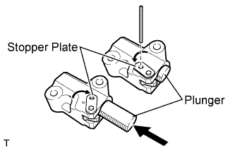
Move the stopper plate upward to release the lock and push the plunger deep into the tensioner.
-
Move the stopper plate downward to set the lock and insert a hexagon wrench into the hole of the stopper plate.
-
Install the chain tensioner with the 2 bolts.
- Torque:
- 10 N*m { 102 kgf*cm, 7 ft.*lbf }
-
Remove the hexagon wrench from the chain tensioner.
-
-
INSTALL NO. 3 CHAIN TENSIONER ASSEMBLY
-
Install the chain tensioner with the 2 bolts.
- Torque:
- 10 N*m { 102 kgf*cm, 7 ft.*lbf }
-
While pushing down the No. 3 chain tensioner, insert a pin with a diameter of 1.0 mm (0.039 in.) into the hole to fix it in place.
-
-
INSTALL CHAIN SUB-ASSEMBLY (for Bank 1)
-
Align the No. 1 chain's orange mark plates with the camshaft timing gear's timing mark and install the chain to the gear as shown in the illustration.
-
Align the No. 1 chain's orange mark plate with the crankshaft timing gear's timing mark and install the chain to the gear as shown in the illustration.
-
Align the No. 2 chain's mark plates (yellow) with the timing marks (1-dot mark) of the camshaft timing gear assembly and camshaft timing exhaust gear assembly and install the No. 2 chain to the gears as shown in the illustration.
Tech Tips
The crankshaft timing gear and camshaft exhaust gear assembly will be installed with the No. 1 and No. 2 chains connected to the gears.
-
Install the crankshaft timing gear to the crankshaft.
-
Align and attach the knock pin of the No. 3 camshaft with the pin hole of the camshaft timing gear assembly.
Tech Tips
Make sure that the arrow is facing upward with respect to the ground.
-
Using the hexagonal portion of the No. 4 camshaft, align and attach the knock pin of the No. 4 camshaft with the pin hole of the camshaft timing exhaust gear assembly.
Note
Because the gears' timing mark positions may shift due to looseness of the No. 1 chain, use the hexagonal portion of the camshaft to hold the No. 3 camshaft in place until the No. 1 chain tensioner is installed.
-
Remove the pin from the No. 2 chain tensioner.
-
-
INSTALL CHAIN TENSIONER SLIPPER (for Bank 1)
Tech Tips
If you cannot install the chain tensioner slipper due to the tension of the chain, use the hexagonal portion of the camshaft to loosen the chain, and then install the chain tensioner.
-
INSTALL NO. 1 CHAIN TENSIONER ASSEMBLY (for Bank 1)
-
Move the stopper plate upward to release the lock and push the plunger deep into the tensioner.
-
Move the stopper plate downward to set the lock and insert a hexagon wrench into the hole of the stopper plate.
-
Install the chain tensioner and a new gasket with the 2 bolts.
- Torque:
- 10 N*m { 102 kgf*cm, 7 ft.*lbf }
-
-
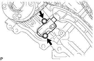
INSTALL NO. 1 CHAIN VIBRATION DAMPER (for Bank 1)
-
Install the vibration damper with the 2 bolts.
- Torque:
- 21 N*m { 214 kgf*cm, 15 ft.*lbf }
-
Remove the hexagon wrench from the No. 1 chain tensioner.
-
-
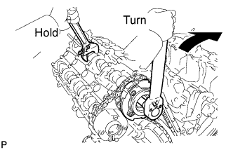
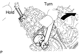
TIGHTEN CAMSHAFT TIMING GEAR ASSEMBLY
-
for Bank 1:
-
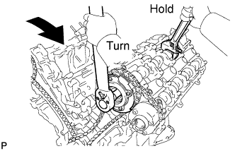
Using a wrench, hold the hexagonal portion of the No. 3 camshaft.
-
Using a 12 mm socket hexagon wrench, tighten the camshaft timing gear assembly with a new bolt.
- Torque:
- 79 N*m { 806 kgf*cm, 58 ft.*lbf }
-
Using a wrench to hold the hexagonal portion of the No. 4 camshaft, tighten the camshaft timing exhaust gear assembly with the bolt.
- Torque:
- 100 N*m { 1020 kgf*cm, 74 ft.*lbf }
-
-
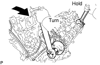
for Bank 2:
-
Using a wrench, hold the hexagonal portion of the No. 1 camshaft.
-
Using a 12 mm socket hexagon wrench, tighten the camshaft timing gear assembly with a new bolt.
- Torque:
- 79 N*m { 806 kgf*cm, 58 ft.*lbf }
-
Using a wrench to hold the hexagonal portion of the No. 2 camshaft, tighten the camshaft timing exhaust gear assembly with the bolt.
- Torque:
- 100 N*m { 1020 kgf*cm, 74 ft.*lbf }
-
-
-
CHECK NO. 1 CYLINDER TO TDC / COMPRESSION
-
Temporarily install the crankshaft pulley bolt.
-
Rotate the crankshaft clockwise and check that the timing marks on the crankshaft timing gear and camshaft timing gears are as shown in the illustration.
-
Remove the crankshaft pulley bolt.
-
-
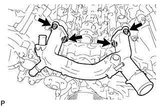
INSTALL WATER INLET PIPE
-
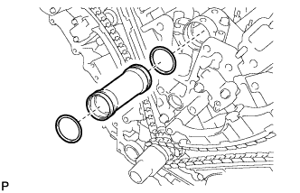
Apply soapy water to 2 new O-rings and install them to the inlet pipe.
-
Install the inlet pipe to the No. 1 heat exchanger cover.
-
-
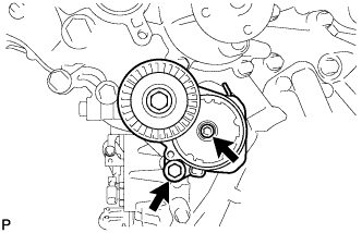
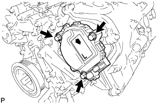
INSTALL WATER PUMP ASSEMBLY
-
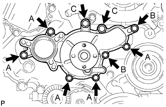
Install the engine water pump and gasket with the 9 bolts as shown in the illustration.
- Torque:
- 20 N*m { 204 kgf*cm, 15 ft.*lbf, for bolt A }
- 23 N*m { 235 kgf*cm, 17 ft.*lbf, for bolt B }
- 47 N*m { 479 kgf*cm, 35 ft.*lbf, for bolt C }
-
-
INSTALL TIMING CHAIN COVER SUB-ASSEMBLY
-
Install a new oil pump gasket.
-
Install a new O-ring.
-
Apply seal packing in a continuous line to the timing chain cover as shown in the following illustration.
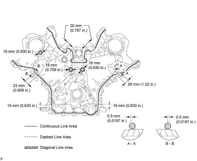
Seal packing Toyota Genuine Seal Packing Black, Three Bond 1207B or equivalent
-
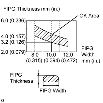
Apply Seal Packing as Follows Area Seal packing diameter Application position from inside edge of cover Continuous Line Area 3.0 to 4.0 mm (0.1181 to 0.1575 in.) 2.5 mm (0.098 in.) Dashed Line Area 6.4 mm (0.2520 in.) or more, or within OK area shown in illustration 0.5 mm (0.020 in.) Diagonal Line Area 3.0 to 4.0 mm (0.1181 to 0.1575 in.) 5.5 mm (0.217 in.)
Note
-
When the contact surfaces are wet, wipe them with an oil-free cloth before applying seal packing.
-
Install the chain cover within 3 minutes and tighten the bolts within 10 minutes after applying seal packing.
-
Do not start the engine for at least 2 hours after installation.
-
-
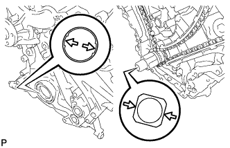
Align the drive rotor spline of the oil pump and the crankshaft as shown in the illustration. Install the spline and chain cover to the crankshaft.
-
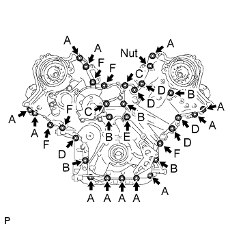
Temporarily install the 30 bolts and nut.
Bolt Length Item Length Thread diameter Bolt A 25 mm (0.984 in.) 8 mm (0.315 in.) Bolt B 55 mm (2.165 in.) 8 mm (0.315 in.) Bolt C 70 mm (2.756 in.) 8 mm (0.315 in.) Bolt D 35 mm (1.378 in.) 10 mm (0.394 in.) Bolt E 55 mm (2.165 in.) 10 mm (0.394 in.) Bolt F 80 mm (3.150 in.) 10 mm (0.394 in.) Note
Make sure that there is no oil on the bolt threads.
-
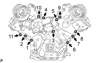
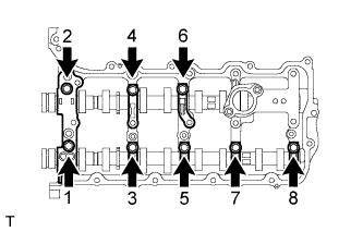
Tighten the 11 bolts in several steps, in the sequence shown in the illustration.
- Torque:
- 47 N*m { 479 kgf*cm, 35 ft.*lbf }
-
Temporarily tighten the belt tensioner with the standard bolt and 6 mm hexagon wrench bolt.
-
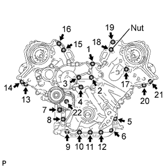
Tighten the 21 bolts and nut in several steps, in the sequence shown in the illustration.
- Torque:
- 23 N*m { 235 kgf*cm, 17 ft.*lbf }
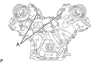
Note
After the installation, if the seal packing has seeped out at the areas labeled A shown in the illustration, wipe it off.
-
Install the 2 new gaskets and the 2 plugs.
- Torque:
- 46 N*m { 469 kgf*cm, 34 ft.*lbf }
-
-
INSTALL OIL CONTROL VALVE FILTER
-
for Bank 1:
-
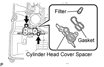
Install the valve filter in the cylinder head.
-
Install a new gasket and the cylinder head cover spacer with the 2 bolts.
- Torque:
- 10 N*m { 102 kgf*cm, 7 ft.*lbf }
-
-
for Bank 2:
-
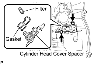
Install the valve filter in the cylinder head.
-
Install a new gasket and the cylinder head cover spacer with the 2 bolts.
- Torque:
- 10 N*m { 102 kgf*cm, 7 ft.*lbf }
-
-
-
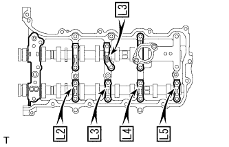
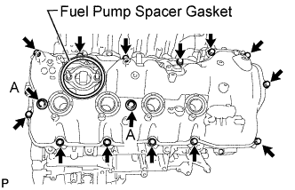
INSTALL CYLINDER HEAD COVER SUB-ASSEMBLY LH
-
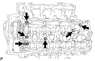
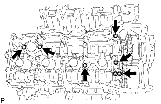
Install 4 new gaskets and 2 new O-rings to the camshaft bearing caps (No. 2, No. 3, No. 7).
-
Install a new gasket to the cylinder head cover.
Note
Remove any oil from the contact surface.
-
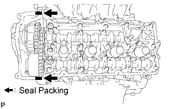
Apply seal packing as shown the illustration.
Seal packing Toyota Genuine Seal Packing Black, Three Bond 1207B or equivalent Note
-
Remove any oil from the contact surface.
-
Install the cylinder head cover within 3 minutes and tighten the bolts within 15 minutes after applying seal packing.
-
Do not start the engine for at least 2 hours after the installation.
-
-
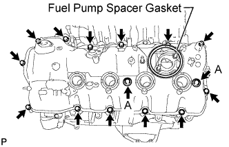
Install the cylinder head cover with 2 new seal washers and the 15 bolts.
- Torque:
- for bolt A
- 21 N*m { 214 kgf*cm, 15 ft.*lbf }
- except bolt A
- 12 N*m { 122 kgf*cm, 9 ft.*lbf }
-
Install the fuel pump spacer gasket.
-
-
INSTALL CYLINDER HEAD COVER SUB-ASSEMBLY RH
-
Install 4 new gaskets and 2 new O-rings to the camshaft bearing caps. (No. 1, No. 3, No. 6).
-
Install a new gasket to the cylinder head cover.
Note
Remove any oil from the contact surface.
-
Apply seal packing as shown the illustration.
Seal packing Toyota Genuine Seal Packing Black, Three Bond 1207B or equivalent Note
-
Remove any oil from the contact surface.
-
Install the cylinder head cover within 3 minutes and tighten the bolts within 15 minutes after applying seal packing.
-
Do not start the engine for at least 2 hours after the installation.
-
-
Install the cylinder head cover with 2 new seal washers and the 15 bolts.
- Torque:
- for bolt A
- 21 N*m { 214 kgf*cm, 15 ft.*lbf }
- except bolt A
- 12 N*m { 122 kgf*cm, 9 ft.*lbf }
-
Install the fuel pump spacer gasket.
-
-
INSTALL SPARK PLUG TUBE GASKET
-
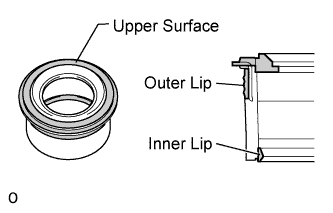
Perform a visual inspection on the spark plug tube gasket.
Standard Area Specified Condition Upper surface No scratches or deformation Outer lip No scratches or deformation Inner lip No scratches -
Install the 8 plug tube gaskets to the cylinder head cover.
-
-
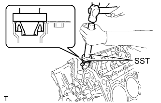
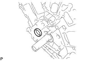
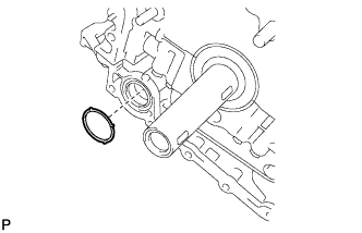
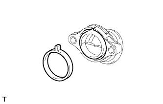
INSTALL TIMING CHAIN CASE OIL SEAL
-
Using SST, tap in a new timing chain case oil seal until its surface is flush with the timing chain case edge.
- SST
- 09223-22010
- 09506-35010
Note
-
Keep the lip free from foreign matter.
-
Do not tap timing chain case oil seal at an angle.
-
-
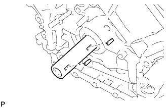
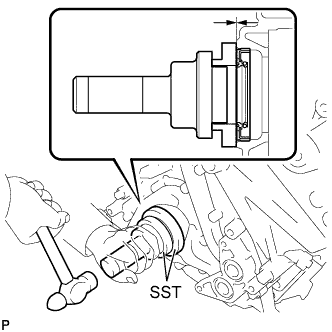
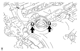
INSTALL CRANKSHAFT PULLEY
-
Align the pulley set key with the key groove of the pulley, and slide on the pulley.
-
Using SST, install the pulley bolt.
- SST
- 09213-54015 ( 90119-08216 )
- 09330-00021
- Torque:
- 300 N*m { 3059 kgf*cm, 221 ft.*lbf }
-
-
INSTALL FRONT WATER BY-PASS JOINT
-
Install the 2 new gaskets and water by-pass joint with the 4 nuts.
- Torque:
- 21 N*m { 214 kgf*cm, 15 ft.*lbf }
-
-
INSTALL OIL FILTER BRACKET (for 2WD)
-
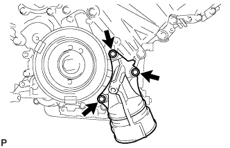
Install 2 new gaskets and the filter bracket with the 3 bolts.
- Torque:
- 21 N*m { 214 kgf*cm, 15 ft.*lbf }
-
-
INSTALL OIL FILTER BRACKET (for AWD)
-
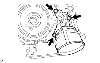
Install 2 new gaskets and the filter bracket with the 3 bolts.
- Torque:
- 21 N*m { 214 kgf*cm, 15 ft.*lbf }
-
-
INSTALL OIL FILTER ELEMENT (for 2WD)
-
Clean the inside of the oil filter cap, the threads and O-ring groove.
-
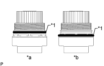
Text in Illustration *1 O-Ring *a CORRECT *b INCORRECT Apply a small amount of engine oil to a new O-ring for the cap, and then install the O-ring to the groove of the oil filter cap.
Note
-
Be sure to install the O-ring in the proper location, otherwise oil may leak.
-
Do not twist the O-ring.
-
-
Set a new oil filter element to the oil filter cap.
-
Remove any dirt or foreign matter from the installation surface of the engine.
-
Apply a small amount of engine oil to the O-ring again and install the oil filter cap.
Note
Do not pinch the O-ring for the cap.
-
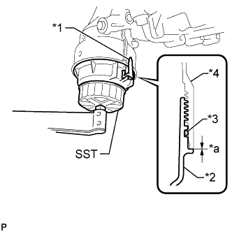
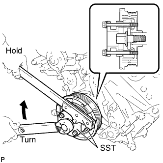
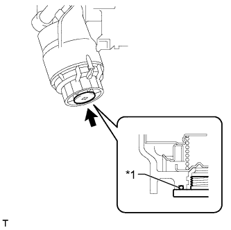
Text in Illustration *1 Oil Filter Bracket Clip *2 Oil Filter Cap *3 O-Ring *4 Oil Filter Bracket *a No Clearance Using SST, tighten the oil filter cap.
- SST
- 09228-06501
- Torque:
- 25 N*m { 255 kgf*cm, 18 ft.*lbf }
Note
-
Do not remove the oil filter bracket clip.
-
Make sure that the oil filter is installed securely as shown in the illustration.
-
Be careful that the O-ring does not get caught between the parts.
-
Text in Illustration *1 O-Ring Apply a small amount of engine oil to a new drain plug O-ring, and install it to the oil filter cap.
Note
Before installing the O-ring, remove any dirt or foreign matter from the installation surface of the oil filter cap.
-
Install the oil filter drain plug.
- Torque:
- 13 N*m { 133 kgf*cm, 10 ft.*lbf }
Note
Be careful that the O-ring does not get caught between the parts.
-
-
INSTALL OIL FILTER ELEMENT (for AWD)
-
Clean the inside of the oil filter cap, the threads and O-ring groove.
-
Text in Illustration *1 O-Ring *a CORRECT *b INCORRECT Apply a small amount of engine oil to a new O-ring for the cap, and then install O-ring to the groove of the oil filter cap.
-
Set a new oil filter element to the oil filter cap.
-
Remove any dirt or foreign matter from the installation surface of the engine.
-
Apply a small amount of engine oil to the O-ring again and install the oil filter cap.
-
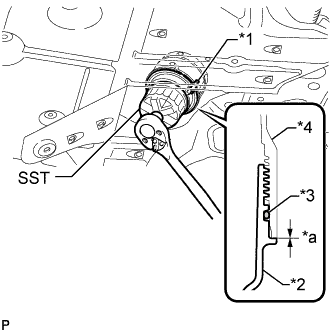
Text in Illustration *1 Oil Filter Bracket Clip *2 Oil Filter Cap *3 O-Ring *4 Oil Filter Bracket *a No Clearance Using SST, tighten the oil filter cap.
- SST
- 09228-06501
- Torque:
- 25 N*m { 255 kgf*cm, 18 ft.*lbf }
Note
-
Do not remove the oil filter bracket clip.
-
Make sure that the oil filter is installed securely as shown in the illustration.
-
Be careful that the O-ring does not get caught between the parts.
-
Text in Illustration *1 O-Ring Apply a small amount of engine oil to a new drain plug O-ring, and install it to the oil filter cap.
Note
Before installing the O-ring, remove any dirt or foreign matter from the installation surface of the oil filter cap.
-
Install the oil filter drain plug.
- Torque:
- 13 N*m { 133 kgf*cm, 10 ft.*lbf }
Note
Be careful that the O-ring does not get caught between the parts.
-
-
INSTALL CYLINDER BLOCK WATER DRAIN COCK SUB-ASSEMBLY
-
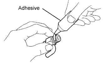
Apply adhesive to 2 or 3 threads of the drain cock.
Adhesive Toyota Genuine Adhesive 1344, Three Bond 1344 or equivalent -
Install the water drain cocks as shown in the illustration.
- Torque:
- 30 N*m { 306 kgf*cm, 22 ft.*lbf }
Note
-
Do not rotate the drain cocks more than 1 revolution (360°) after tightening the drain cocks with the specified torque.
-
Do not loosen the drain cocks to adjust them. If an adjustment is necessary, remove the drain cocks and reinstall them.
-
Install the water drain cock plugs to the water drain cocks.
- Torque:
- 13 N*m { 133 kgf*cm, 10 ft.*lbf }
-
-
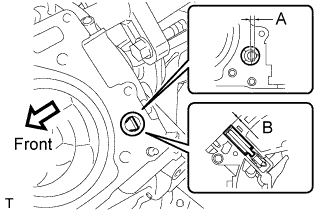
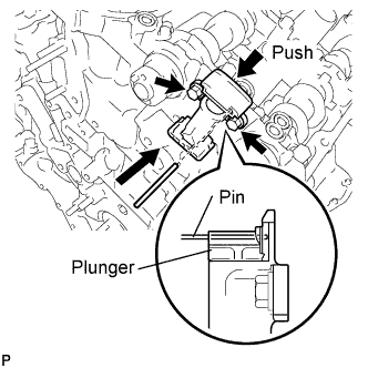
INSTALL CAMSHAFT TIMING CONTROL WITH EDU MOTOR ASSEMBLY LH
-
Turn the camshaft timing gear's eccentric shaft keyway part counterclockwise by hand and set it to the maximum retard angle.
Tech Tips
-
When the cam of the camshaft lifts the valve, the eccentric shaft becomes difficult to turn.
-
The position where the eccentric shaft stops is the maximum retard angle.
Note
When turning the eccentric shaft keyway part, do not use any tools as the keyway part may be damaged.
-
-
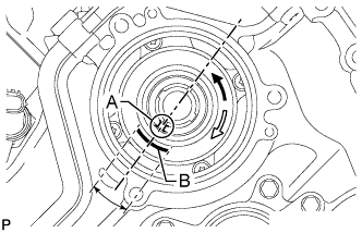
Turn the eccentric shaft clockwise until the groove labeled A and mark labeled B are aligned as shown in the illustration.
Tech Tips
Make sure that the groove labeled A is positioned as close as possible to the center of the mark labeled B.
-
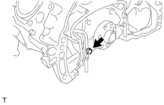
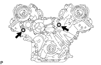
Install a new O-ring to the timing chain cover.
-
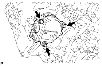
Align the joint of the camshaft timing control with EDU motor assembly LH and the keyway of the camshaft timing gear assembly, and install the camshaft timing control with EDU motor assembly LH with the 3 bolts.
- Torque:
- 21 N*m { 214 kgf*cm, 15 ft.*lbf }
Note
-
Do not allow foreign matter to contact the oil seal face of the camshaft timing control with EDU motor assembly LH (connecting surface with timing chain cover).
-
When installing the camshaft timing control with EDU motor assembly LH, do not use excessive force.
-
Do not drop the camshaft timing control with EDU motor assembly LH. If dropped, replace it.
-
Do not disassemble the camshaft timing control with EDU motor assembly LH. If disassembled, replace it.
Tech Tips
-
Check that [L] is printed on the label of the camshaft timing control with EDU motor assembly LH.
-
When installing the camshaft timing control with EDU motor assembly LH, be sure to align the timing chain cover knock pin with the camshaft timing control with EDU motor assembly LH pin hole.
-
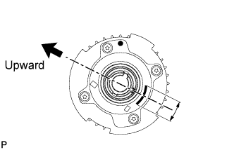
Install the camshaft timing control with EDU motor assembly LH with the arrow facing upward.
-
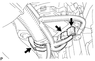
Connect the 2 camshaft timing control with EDU motor assembly LH connectors and engine wire clamp.
-
-
INSTALL CAMSHAFT TIMING CONTROL WITH EDU MOTOR ASSEMBLY RH
-
Turn the camshaft timing gear's eccentric shaft keyway part counterclockwise by hand and set it to the maximum retard angle.
Tech Tips
-
When the cam of the camshaft lifts the valve, the eccentric shaft becomes difficult to turn.
-
The position where the eccentric shaft stops is the maximum retard angle.
Note
When turning the eccentric shaft keyway part, do not use any tools as the keyway part may be damaged.
-
-
Turn the eccentric shaft clockwise until the groove labeled A and mark labeled B are aligned as shown in the illustration.
Tech Tips
Make sure that the groove labeled A is positioned as close as possible to the center of the mark labeled B.
-
Install a new O-ring to the timing chain cover.
-
Align the joint of the camshaft timing control with EDU motor assembly RH and the keyway of the camshaft timing gear assembly, and install the camshaft timing control with EDU motor assembly RH with the 3 bolts.
- Torque:
- 21 N*m { 214 kgf*cm, 15 ft.*lbf }
Note
-
Do not allow foreign matter to contact the oil seal face of the camshaft timing control with EDU motor assembly RH (connecting surface with timing chain cover).
-
When installing the camshaft timing control with EDU motor assembly RH, do not use excessive force.
-
Do not drop the camshaft timing control with EDU motor assembly RH. If dropped, replace it.
-
Do not disassemble the camshaft timing control with EDU motor assembly RH. If disassembled, replace it.
Tech Tips
-
Check that [R] is printed on the label of the camshaft timing control with EDU motor assembly RH.
-
When installing the camshaft timing control with EDU motor assembly RH, be sure to align the timing chain cover knock pin with the camshaft timing control with EDU motor assembly RH pin hole.
-
Install the camshaft timing control with EDU motor assembly RH with the arrow facing upward.
-
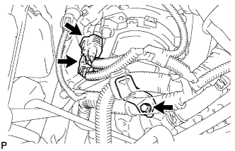
Install the engine wire bracket with the bolt.
- Torque:
- 12 N*m { 122 kgf*cm, 9 ft.*lbf }
-
Connect the 2 camshaft timing control with EDU motor assembly RH connectors.
-
-
INSTALL CAMSHAFT TIMING OIL CONTROL VALVE ASSEMBLY
-
for Bank 1:
-
Apply a light coat of engine oil to a new O-ring.
-
Install the O-ring to the oil control valve.
-
Install the oil control valve with the bolt.
- Torque:
- 10 N*m { 102 kgf*cm, 7 ft.*lbf }
-
-
for Bank 2:
-
Apply a light coat of engine oil to a new O-ring.
-
Install the O-ring to the oil control valve.
-
Install the oil control valve with the bolt.
- Torque:
- 10 N*m { 102 kgf*cm, 7 ft.*lbf }
-
-
-
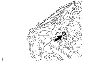
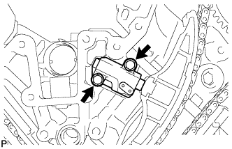
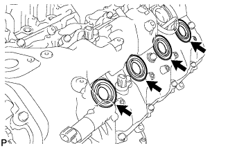
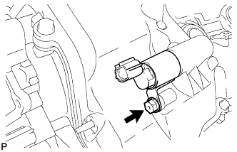
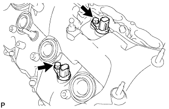
INSTALL CRANKSHAFT POSITION SENSOR
-
Install the crankshaft position sensor with the bolt.
- Torque:
- 10 N*m { 102 kgf*cm, 7 ft.*lbf }
-
-
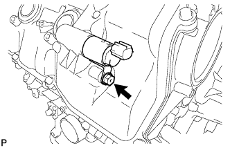
INSTALL CAMSHAFT POSITION SENSOR
-
Install the camshaft position sensor with the bolt.
- Torque:
- 10 N*m { 102 kgf*cm, 7 ft.*lbf }
-
-
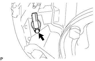
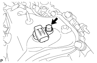
INSTALL VVT SENSOR
-
for Bank 1:
-
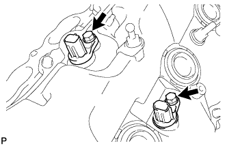
Install the 2 VVT sensors with the 2 bolts.
- Torque:
- 10 N*m { 102 kgf*cm, 7 ft.*lbf }
-
-
for Bank 2:
-
Install the 2 VVT sensors with the 2 bolts.
- Torque:
- 10 N*m { 102 kgf*cm, 7 ft.*lbf }
-
-
-
INSTALL SPARK PLUG
-
Using a 16 mm plug wrench, install the 8 spark plugs.
- Torque:
- 21 N*m { 214 kgf*cm, 15 ft.*lbf }
-
-
INSTALL OIL FILLER CAP HOUSING
-
Align the protrusion of a new gasket with the cutout of the oil filler cap housing, and install the gasket to the housing.
-
Install the cap housing with the 2 bolts.
- Torque:
- 10 N*m { 102 kgf*cm, 7 ft.*lbf }
-
-
INSTALL OIL FILLER CAP SUB-ASSEMBLY