DRIVE BELT INSTALLATION

-
INSTALL V-RIBBED BELT
-
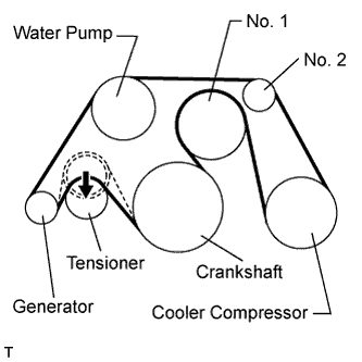
Install the V-ribbed belt as shown in the illustration.
Note
Check that the V-ribbed belt is properly set to each pulley.
-
Rotate the tensioner pulley counterclockwise, and then remove the fix bar.
-
-
-
INSTALL INTAKE AIR CONNECTOR PIPE
-
Install the intake air sound creator.
Tech Tips
Only perform this procedure when replacement of the intake air sound creator is necessary.
-
Install the intake air sound creator with the bolt and hose clamp.
- Torque:
- 2.0 N*m { 20 kgf*cm, 18 in.*lbf }
-
-
Align the protrusion of the intake air resonator with the cutout of the bracket and insert the protrusion.
-
Install the intake air connector pipe with the 3 hose clamps.
- Torque:
- for intake air connector pipe and throttle body
- 4.8 N*m { 49 kgf*cm, 42 in.*lbf }
- for intake air connector pipe and air cleaner cap
- 3.8 N*m { 39 kgf*cm, 34 in.*lbf }
Tech Tips
-
Insert the protrusion of the intake air connector pipe into the hole of the hose clamp.
-
The intake air connector pipe and throttle body clamp can be tightened within the range of 4.0 N*m (41 kgf*cm, 35 in.*lbf) to 5.5 N*m (56 kgf*cm, 49 in.*lbf), and the intake air connector pipe and air cleaner cap clamp can be tightened within the range of 2.0 N*m (20 kgf*cm, 18 in.*lbf) to 5.5 N*m (56 kgf*cm, 49 in.*lbf).
-
Attach the 2 wire harness clamps.
-
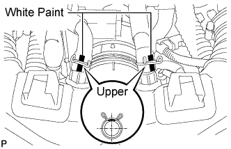
Connect the No. 1 and No. 2 ventilation hoses to the intake air connector pipe.
Tech Tips
-
Position the claws of the clamps as shown in the illustration.
-
Install the clamps so that they are within the hose's paint marks.
-
-
-
INSTALL NO. 1 AIR CLEANER INLET
-
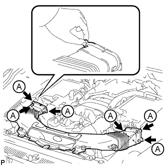
Align the holes with the connection areas labeled A, and attach the No. 1 air cleaner inlet.
-
Install the No. 1 air cleaner inlet with the 2 bolts.
- Torque:
- 5.0 N*m { 51 kgf*cm, 44 in.*lbf }
-
-
INSTALL AIR CLEANER INLET COVER SUB-ASSEMBLY
-
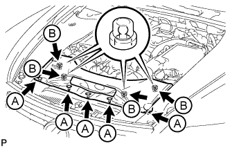
Attach the 4 clips labeled B.
Note
-
Make sure the clips are attached securely.
-
Attaching the clips forcefully or hitting the top of the clips may damage them.
-
-
Install the air cleaner inlet cover sub-assembly with the 5 clips labeled A.
-
-
INSTALL V-BANK COVER SUB-ASSEMBLY
-
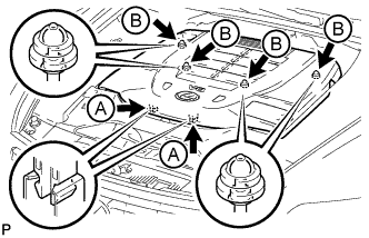
Slide the cover from the vehicle front toward the rear of the vehicle to attach the 2 clips labeled A, and then attach the 4 clips labeled B to install the V bank cover sub-assembly.
Note
-
Make sure the clips are attached securely.
-
Attaching the clips forcefully or hitting the top of the clips may damage them.
-
When attaching the clips labeled A, be sure to slide the cover from the front of the vehicle toward the rear of the vehicle.
-
-