CYLINDER HEAD INSPECTION

-
INSPECT CYLINDER HEAD SUB-ASSEMBLY
-

Using a precision straightedge and feeler gauge, measure the warpage of the contact surfaces of the cylinder block and manifold.
Standard warpage Item Specified Condition Cylinder head lower side 0.05 mm (0.0020 in.) Intake side 0.08 mm (0.0031 in.) Exhaust side 0.05 mm (0.0020 in.) Maximum warpage 0.10 mm (0.0039 in.) If the warpage is greater than the maximum, replace the cylinder head.
-

Using a dye penetrant, check the intake ports, exhaust ports and cylinder surface for cracks.
If cracked, replace the cylinder head.
-
-
INSPECT INTAKE VALVE
-
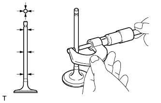
Using a micrometer, measure the diameter of the valve stem.
Standard valve stem diameter 5.470 to 5.485 mm (0.2154 to 0.2159 in.) -
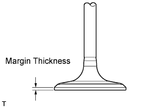
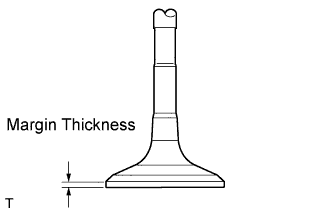
Using a vernier caliper, measure the valve head margin thickness.
Standard margin thickness 1.25 mm (0.0492 in.) Minimum margin thickness 0.50 mm (0.0197 in.) If the margin thickness is less than the minimum, replace the intake valve.
-
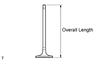
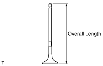
Using a vernier caliper, measure the valve's overall length.
Standard overall length 105.85 mm (4.1673 in.) Minimum overall length 105.35 mm (4.1476 in.) If the overall length is less than the minimum, replace the intake valve.
-
-
INSPECT EXHAUST VALVE
-
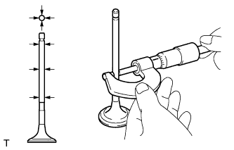
Using a micrometer, measure the diameter of the valve stem.
Standard valve stem diameter 5.465 to 5.480 mm (0.2152 to 0.2157 in.) -
Using a vernier caliper, measure the valve head margin thickness.
Standard margin thickness 1.4 mm (0.0551 in.) Minimum margin thickness 0.50 mm (0.0197 in.) If the margin thickness is less than the minimum, replace the exhaust valve.
-
Using a vernier caliper, measure the valve's overall length.
Standard overall length 110.40 mm (4.3465 in.) Minimum overall length 109.90 mm (4.3268 in.) If the overall length is less than the minimum, replace the exhaust valve.
-
-
INSPECT INTAKE VALVE SEAT
-
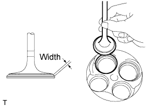
Apply a light coat of Prussian blue to the valve face.
-
Lightly press the valve face against the valve seat.
Tech Tips
Do not rotate the valve while pressing the valve.
-
Check the valve face and valve seat.
-
Check that the contact surfaces of the valve seat and valve face are in the middle area of their respective surfaces, with the width between 1.1 to 1.5 mm (0.0433 to 0.0591 in.).
If not, correct the valve seat.
-
Check that the contact surfaces of the valve seat and valve face are even around the entire valve seat.
If not, correct the valve seat.
-
-
-
INSPECT EXHAUST VALVE SEAT
-
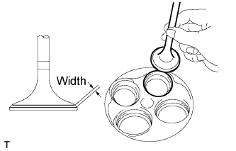
Apply a light coat of Prussian blue to the valve face.
-
Lightly press the valve face against the valve seat.
-
Check the valve face and valve seat.
-
Check that the contact surfaces of the valve seat and valve face are in the middle area of their respective surfaces, with the width between 1.1 to 1.5 mm (0.0433 to 0.0591 in.).
If not, correct the valve seat.
-
Check that the contact surface of the valve seat and valve face are even around the entire valve seat.
If not, correct the valve seat.
-
-
-
INSPECT COMPRESSION SPRING
-
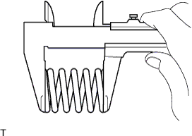
Using a vernier caliper, measure the free length of the inner compression spring.
Standard Free Length Item Specified Condition Orange 51.70 mm (2.04 in.) Light Green 49.73 mm (1.96 in.) Pink or No Paint Mark 48.05 mm (1.89 in.) If the free length is not as specified, replace the spring.
Tech Tips
-
The colors in the chart above indicate the colors of the paint mark on the inner compression spring.
-
The paint mark differs depending on the type of inner compression spring.
-
-
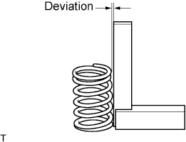
Using a steel square, measure the deviation of the inner compression spring.
Maximum deviation 1.0 mm (0.0394 in.) Maximum angle (reference) 2° If the deviation is greater than the maximum, replace the spring.
-
-
INSPECT VALVE GUIDE BUSH OIL CLEARANCE
-
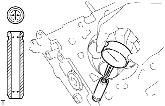
Using a caliper gauge, measure the inside diameter of the guide bush.
Standard bush inside diameter 5.51 to 5.53 mm (0.2169 to 0.2177 in.) -
Subtract the valve stem diameter measurement from the guide bush inside diameter measurement.
Standard oil clearance Item Specified Condition Intake 0.025 to 0.060 mm (0.0010 to 0.0024 in.) Exhaust 0.030 to 0.065 mm (0.0012 to 0.0026 in.) Maximum oil clearance Item Specified Condition Intake 0.08 mm (0.0031 in.) Exhaust 0.10 mm (0.0039 in.) If the clearance is greater than the maximum, replace the valve and guide bush.
-
-
INSPECT CAMSHAFT THRUST CLEARANCE
-
Inspect the bank 1 camshafts.
-
Install the bank 1 camshafts.
-
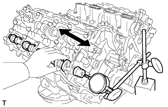
Using a dial indicator, measure the thrust clearance while moving the camshaft back and forth.
Standard thrust clearance 0.08 to 0.13 mm (0.0031 to 0.0051 in.) Maximum thrust clearance 0.15 mm (0.0059 in.) If the thrust clearance is greater than the maximum, replace the cylinder head. If the thrust surface is damaged, replace the camshaft.
-
-
Inspect the bank 2 camshafts.
-
Install the bank 2 camshafts.
-
Using a dial indicator, measure the thrust clearance while moving the camshaft back and forth.
Standard thrust clearance 0.08 to 0.13 mm (0.0031 to 0.0051 in.) Maximum thrust clearance 0.15 mm (0.0059 in.) If the thrust clearance is greater than the maximum, replace the cylinder head. If the thrust surface is damaged, replace the camshaft.
-
-