MASS AIR FLOW METER INSTALLATION

-
INSTALL MASS AIR FLOW METER SUB-ASSEMBLY (for Bank 1)
-
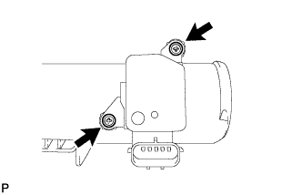
Install the mass air flow meter sub-assembly with the 2 screws.
- Torque:
- 1.0 N*m { 10 kgf*cm, 9 in.*lbf }
Note
-
If the screw is tightened excessively, the screw hole may be damaged.
-
Make sure the O-ring is not pinched.
-
-
INSTALL MASS AIR FLOW METER SUB-ASSEMBLY (for Bank 2)
-
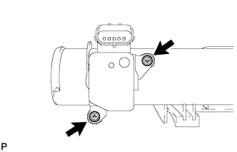
Install the mass air flow meter sub-assembly with the 2 screws.
- Torque:
- 1.0 N*m { 10 kgf*cm, 9 in.*lbf }
Note
-
If the screw is tightened excessively, the screw hole may be damaged.
-
Make sure the O-ring is not pinched.
-
-
INSTALL AIR CLEANER CAP SUB-ASSEMBLY LH
-
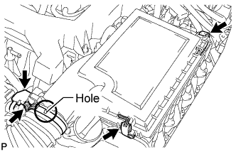
Install the air cleaner cap sub-assembly LH to the air cleaner case with the 2 clips.
- Torque:
- for hose clamp
- 3.8 N*m { 39 kgf*cm, 34 in.*lbf }
Tech Tips
Insert the protrusion of the air cleaner hose into the hole of the hose clamp.
-
Connect the mass air flow meter connector.
-
-
INSTALL AIR CLEANER CAP SUB-ASSEMBLY RH
-
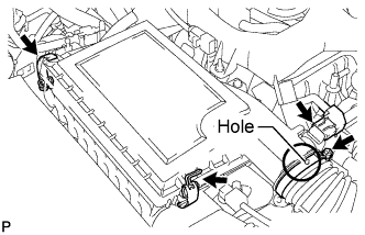
Install the air cleaner cap sub-assembly RH to the air cleaner case with the 2 clips.
- Torque:
- for hose clamp
- 3.8 N*m { 39 kgf*cm, 34 in.*lbf }
Tech Tips
Insert the protrusion of the air cleaner hose into the hole of the hose clamp.
-
Connect the mass air flow meter connector.
-
-
INSTALL V-BANK COVER SUB-ASSEMBLY
-
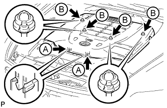
Slide the cover from the vehicle front toward the rear of the vehicle to attach the 2 clips labeled A, and then attach the 4 clips labeled B to install the V bank cover sub-assembly.
Note
-
Make sure the clips are attached securely.
-
Attaching the clips forcefully or hitting the top of the clips may damage them.
-
When attaching the clips labeled A, be sure to slide the cover from the front of the vehicle toward the rear of the vehicle.
-
-