CAMSHAFT OIL CONTROL VALVE INSTALLATION

-
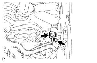
INSTALL CAMSHAFT TIMING OIL CONTROL VALVE ASSEMBLY (for Bank 1)
-
Apply a light coat of engine oil to a new O-ring, and install it to the camshaft timing oil control valve assembly.
-
Install the camshaft timing oil control valve assembly with the bolt.
- Torque:
- 10 N*m { 102 kgf*cm, 7 ft.*lbf }
Note
-
Do not allow foreign matter to contact the oil seal face of the camshaft timing oil control valve assembly (connecting surface with cylinder head cover).
-
Be careful that the O-ring is not cracked or moved out of place when installing the camshaft timing oil control valve assembly.
-
Connect the camshaft timing oil control valve assembly connector.
-
-
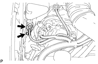
INSTALL CAMSHAFT TIMING OIL CONTROL VALVE ASSEMBLY (for Bank 2)
-
Apply a light coat of engine oil to a new O-ring, and install it to the camshaft timing oil control valve assembly.
-
Install the camshaft timing oil control valve assembly with the bolt.
- Torque:
- 10 N*m { 102 kgf*cm, 7 ft.*lbf }
Note
-
Do not allow foreign matter to contact the oil seal face of the camshaft timing oil control valve assembly (connecting surface with cylinder head cover).
-
Be careful that the O-ring is not cracked or moved out of place when installing the camshaft timing oil control valve assembly.
-
Connect the camshaft timing oil control valve assembly connector.
-
-
INSTALL NO. 1 AIR CLEANER INLET
-
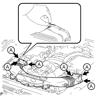
Align the holes with the connection areas labeled A, and attach the No. 1 air cleaner inlet.
-
Install the No. 1 air cleaner inlet with the 2 bolts.
- Torque:
- 5.0 N*m { 51 kgf*cm, 44 in.*lbf }
-
-
INSTALL AIR CLEANER INLET COVER SUB-ASSEMBLY
-
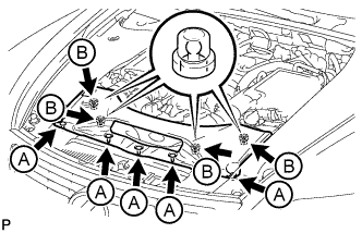
Attach the 4 clips labeled B.
Note
-
Make sure the clips are attached securely.
-
Attaching the clips forcefully or hitting the top of the clips may damage them.
-
-
Install the air cleaner inlet cover sub-assembly with the 5 clips labeled A.
-
-
INSTALL V-BANK COVER SUB-ASSEMBLY
-
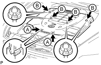
Slide the cover from the vehicle front toward the rear of the vehicle to attach the 2 clips labeled A, and then attach the 4 clips labeled B to install the V bank cover sub-assembly.
Note
-
Make sure the clips are attached securely.
-
Attaching the clips forcefully or hitting the top of the clips may damage them.
-
When attaching the clips labeled A, be sure to slide the cover from the front of the vehicle toward the rear of the vehicle.
-
-
-
DRIVING TEST
-
After the engine is warmed up, perform the driving test. Then check that the oil control valve operates normally.
-