SFI SYSTEM, Diagnostic DTC:P2A00, P2A03

| DTC Code | DTC Name |
|---|---|
| P2A00 | A/F Sensor Circuit Slow Response (Bank 1 Sensor 1) |
| P2A03 | A/F Sensor Circuit Slow Response (Bank 2 Sensor 1) |
DESCRIPTION
Refer to DTC P2195 Click here.
Tech Tips
-
DTC P2A00 indicates malfunctions related to the bank 1 A/F sensor.
-
DTC P2A03 indicates malfunctions related to the bank 2 A/F sensor.
-
Bank 1 refers to the bank that includes No. 1 cylinder.
-
Bank 2 refers to the bank that includes No. 2 cylinder.
-
Sensor 1 refers to the sensor mounted in front of the Three-Way Catalytic Converter (TWC) and located near the engine assembly.
| DTC No. | DTC Detection Condition | Trouble Area |
|---|---|---|
| P2A00 P2A03 |
Calculated value for air-fuel ratio (A/F) sensor response rate deterioration level is less than threshold |
|
MONITOR DESCRIPTION
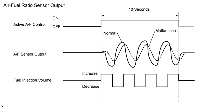
After the engine is warmed up, the ECM performs air-fuel ratio feedback control to maintain the air-fuel ratio at the stoichiometric level. In addition, active A/F control is performed for approximately 10 seconds after preconditions are met in order to measure the A/F sensor response rate. During active A/F control, the ECM forcibly increases and decreases the injection volume a certain amount, based on the stoichiometric air-fuel ratio learned during normal air-fuel ratio control, and measures the A/F sensor response rate. The ECM receives a signal from the A/F sensor while performing active A/F control and uses it to calculate the A/F sensor response rate deterioration level.
If the value for the A/F sensor response rate deterioration level is less than the threshold, the ECM interprets this as a malfunction and sets the DTC.
CONFIRMATION DRIVING PATTERN
Tech Tips
Performing this confirmation pattern will activate the A/F sensor response monitor.
-
(a) Connect the intelligent tester to the DLC3.
-
(b) Turn the engine switch on (IG).
-
(c) Turn the tester ON.
-
(d) Clear DTCs Click here.
-
(e) Enter the following menus: Powertrain / Engine / Data List / Monitor Status.
-
(f) Check that O2S (A/FS) Monitor is Incmpl.
-
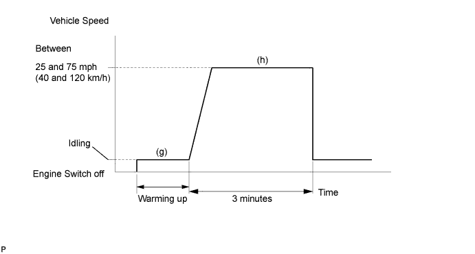
(g) Start the engine and warm it up.
-
(h) Drive the vehicle at between 25 mph and 75 mph (40 km/h and 120 km/h) for 3 minutes. However, the vehicle should be driven at a constant speed.
-
(i) Check O2S (A/FS) Monitor is Incmpl.
-
(j) Enter the following menus: Powertrain / Engine / DTC / Pending.
-
(k) Check if any DTCs (any pending DTCs) are set.
WIRING DIAGRAM
Refer to DTC P2195 Click here.
INSPECTION PROCEDURE
Tech Tips
-
DTC P2A00 or P2A03 may be also set, when the air-fuel ratio is stuck rich or lean.
-
A low A/F sensor voltage could be caused by a rich air-fuel mixture. Check for conditions that would cause the engine to run rich.
-
A high A/F sensor voltage could be caused by a lean air-fuel mixture. Check for conditions that would cause the engine to run lean.
-
Read freeze frame data using the intelligent tester. Freeze frame data records the engine condition when malfunctions are detected. When troubleshooting, freeze frame data can help determine if the vehicle was moving or stationary, if the engine was warmed up or not, if the air-fuel ratio was lean or rich, and other data from the time the malfunction occurred.
PROCEDURE
-
CHECK ANY OTHER DTCS OUTPUT (IN ADDITION TO DTC P2A00 AND/OR P2A03)
-
Connect the intelligent tester to the DLC3.
-
Turn the engine switch on (IG).
-
Turn the tester ON.
-
Enter the following menus: Powertrain / Engine / DTC.
-
Read DTCs.
Result Display (DTC Output) Proceed to P2A00 and/or P2A03 A P2A00 and/or P2A03 and other DTCs B Tech Tips
If any DTCs other than P2A00 or P2A03 are output, troubleshoot those DTCs first.
B 
GO TO DTC CHART Click here
A 
-
-
INSPECT AIR FUEL RATIO SENSOR (HEATER RESISTANCE)
-
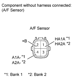
Disconnect the E47*1 or E48*2 A/F sensor connector.
Tech Tips
*1: Bank 1 Sensor 1
*2: Bank 2 Sensor 1
-
Measure the resistance according to the value(s) in the table below.
Standard resistance (Bank 1 Sensor 1) Tester Connection Condition Specified Condition 1 (HA1A) - 2 (+B) 20°C (68°F) 1.8 to 3.4 Ω 1 (HA1A) - 4 (A1A-) Always 10 kΩ or higher Standard resistance (Bank 2 Sensor 1) Tester Connection Condition Specified Condition 1 (HA2A) - 2 (+B) 20°C (68°F) 1.8 to 3.4 Ω 1 (HA2A) - 4 (A2A-) Always 10 kΩ or higher Result Result Proceed to OK A NG (for 2WD) B NG (for AWD) C
B
REPLACE AIR FUEL RATIO SENSOR Click here
C
REPLACE AIR FUEL RATIO SENSOR Click here
A
-
-
CHECK HARNESS AND CONNECTOR (A/F SENSOR - ECM)
-
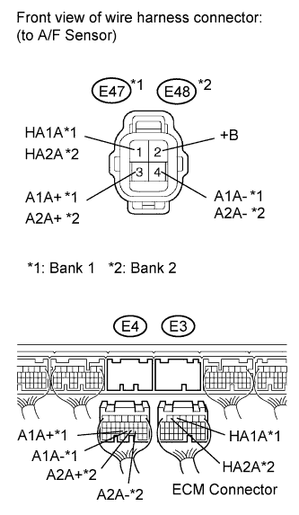
Disconnect the E47 and E48 A/F sensor connectors.
-
Turn the engine switch on (IG).
-
Measure the voltage according to the value(s) in the table below.
Standard voltage Tester Connection Switch Condition Specified Condition E47-2 (+B) - Body ground Engine switch on (IG) 11 to 14 V E48-2 (+B) - Body ground Engine switch on (IG) 11 to 14 V -
Turn the engine switch off.
-
Disconnect the E3 and E4 ECM connectors.
-
Measure the resistance according to the value(s) in the table below.
Standard resistance (Check for open) Tester Connection Condition Specified Condition E47-1 (HA1A) - E3-5 (HA1A) Always Below 1 Ω E47-3 (A1A+) - E4-23 (A1A+) Always Below 1 Ω E47-4 (A1A-) - E4-22 (A1A-) Always Below 1 Ω E48-1 (HA2A) - E3-6 (HA2A) Always Below 1 Ω E48-3 (A2A+) - E4-21 (A2A+) Always Below 1 Ω E48-4 (A2A-) - E4-20 (A2A-) Always Below 1 Ω Standard resistance (Check for short) Tester Connection Condition Specified Condition E47-1 (HA1A) or E3-5 (HA1A) - Body ground Always 10 kΩ or higher E47-3 (A1A+) or E4-23 (A1A+) - Body ground Always 10 kΩ or higher E47-4 (A1A-) or E4-22 (A1A-) - Body ground Always 10 kΩ or higher E48-1 (HA2A) or E3-6 (HA2A) - Body ground Always 10 kΩ or higher E48-3 (A2A+) or E4-21 (A2A+) - Body ground Always 10 kΩ or higher E48-4 (A2A-) or E4-20 (A2A-) - Body ground Always 10 kΩ or higher 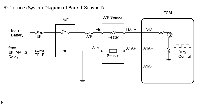
NG
REPAIR OR REPLACE HARNESS OR CONNECTOR
OK
-
-
PERFORM CONFIRMATION DRIVING PATTERN
NEXT
-
CHECK WHETHER DTC OUTPUT RECURS (DTC P2A00 AND/OR P2A03)
-
Connect the intelligent tester to the DLC3.
-
Turn the engine switch on (IG) and turn the tester ON.
-
Enter the following menus: Powertrain / Engine / DTC / Pending.
-
Read the DTCs.
Result Display (DTC Output) Proceed to P2A00 and/or P2A03 A No output B
B
CHECK FOR INTERMITTENT PROBLEMS Click here
A
-
-
REPLACE AIR FUEL RATIO SENSOR
-
Replace the air fuel ratio sensor.
NEXT
-
-
PERFORM CONFIRMATION DRIVING PATTERN
NEXT
-
CHECK WHETHER DTC OUTPUT RECURS (DTC P2A00 AND/OR P2A03)
-
Connect the intelligent tester to the DLC3.
-
Turn the engine switch on (IG) and turn the tester ON.
-
Enter the following menus: Powertrain / Engine / DTC / Pending.
-
Read the DTCs.
Result Display (DTC Output) Proceed to No output A P2A00 and/or P2A03 B
B
CHECK EXTREMELY RICH OR LEAN ACTUAL AIR FUEL RATIO (REFER TO DTC P0171 PROCEDURE) Click here
A 
END
-