SFI SYSTEM, Diagnostic DTC:P0136, P0137, P0138, P0156, P0157, P0158

| DTC Code | DTC Name |
|---|---|
| P0136 | Oxygen Sensor Circuit Malfunction (Bank 1 Sensor 2) |
| P0137 | Oxygen Sensor Circuit Low Voltage (Bank 1 Sensor 2) |
| P0138 | Oxygen Sensor Circuit High Voltage (Bank 1 Sensor 2) |
| P0156 | Oxygen Sensor Circuit Malfunction (Bank 2 Sensor 2) |
| P0157 | Oxygen Sensor Circuit Low Voltage (Bank 2 Sensor 2) |
| P0158 | Oxygen Sensor Circuit High Voltage (Bank 2 Sensor 2) |
DESCRIPTION
Tech Tips
Sensor 2 refers to the sensor mounted behind the Three-Way Catalytic Converter (TWC) and located far from the engine assembly.
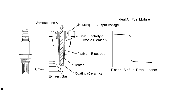
In order to obtain a high purification rate of the carbon monoxide (CO), hydrocarbon (HC) and nitrogen oxide (NOx) components in the exhaust gas, a TWC (Three-Way Catalytic Converter) is used. For the most efficient use of the TWC, the air-fuel ratio must be precisely controlled so that it is always close to the stoichiometric air-fuel level. For the purpose of helping the ECM to deliver accurate air-fuel ratio control, a Heated Oxygen (HO2) sensor is used.
The HO2 sensor is located behind the TWC, and detects the oxygen concentration in the exhaust gas. Since the sensor is integrated with the heater that heats the sensing portion, it is possible to detect the oxygen concentration even when the intake air volume is low (the exhaust gas temperature is low).
When the air-fuel ratio becomes lean, the oxygen concentration in the exhaust gas is rich. The HO2 sensor informs the ECM that the post-TWC air-fuel ratio is lean (low voltage, i.e. less than 0.45 V).
Conversely, when the air-fuel ratio is richer than the stoichiometric air-fuel level, the oxygen concentration in the exhaust gas becomes lean. The HO2 sensor informs the ECM that the post-TWC air-fuel ratio is rich (high voltage, i.e. more than 0.45 V). The HO2 sensor has the property of changing its output voltage drastically when the air-fuel ratio is close to the stoichiometric level.
The ECM uses the supplementary information from the HO2 sensor to determine whether the air-fuel ratio after the TWC is rich or lean, and adjusts the fuel injection time accordingly. Thus, if the HO2 sensor is working improperly due to internal malfunctions, the ECM is unable to compensate for deviations in the primary air-fuel ratio control.
| DTC No. | DTC Detection Condition | Trouble Area |
|---|---|---|
| P0136 P0156 |
|
|
| P0137 P0157 |
|
|
| P0138 P0158 |
|
|
MONITOR DESCRIPTION
-
Active Air-Fuel Ratio Control
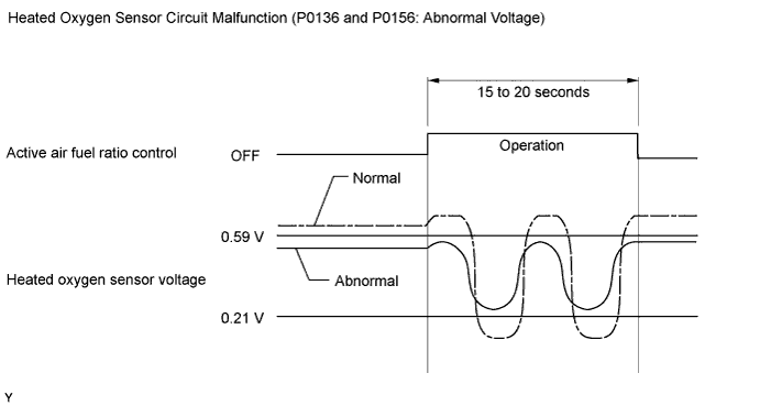
The ECM usually performs air-fuel ratio feedback control so that the Air-Fuel Ratio (A/F) sensor output indicates a near stoichiometric air-fuel level. This vehicle includes active air-fuel ratio control in addition to regular air-fuel ratio control. The ECM performs active air-fuel ratio control to detect any deterioration in the Three-Way Catalytic Converter (TWC) and Heated Oxygen (HO2) sensor malfunctions (refer to the diagram below).
Active air-fuel ratio control is performed for approximately 15 to 20 seconds while driving with a warm engine. During active air-fuel ratio control, the air-fuel ratio is forcibly regulated to become lean or rich by the ECM. If the ECM detects a malfunction, one of the following DTCs is set: DTC P0136 or P0156 (abnormal voltage output), P0137 or P0157 (open circuit) or P0138 or P0158 (short circuit).
-
Abnormal Voltage Output of HO2 Sensor (DTCs P0136 and P0156)
While the ECM is performing active air-fuel ratio control, the air-fuel ratio is forcibly regulated to become rich or lean. If the sensor is not functioning properly, the voltage output variation is small. For example, when the HO2 sensor voltage does not decrease to less than 0.21 V and does not increase to more than 0.59 V during active air-fuel ratio control, the ECM determines that the sensor voltage output is abnormal and sets DTCs P0136 and P0156.
-
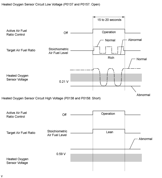
Open or Short in Heated Oxygen (HO2) Sensor Circuit (DTCs P0137 and P0157 or P0138 and P0158)
During active air-fuel ratio control, the ECM calculates the Oxygen Storage Capacity (OSC)*of the Three-Way Catalytic Converter (TWC) by forcibly regulating the air-fuel ratio to become rich or lean.
If the HO2 sensor has an open or short, or the voltage output of the sensor noticeably decreases, the OSC indicates an extraordinarily high value. Even if the ECM attempts to continue regulating the air-fuel ratio to become rich or lean, the HO2 sensor output does not change.
While performing active air-fuel ratio control, when the target air-fuel ratio is rich and the HO2 sensor voltage output is 0.21 V or less (lean), the ECM interprets this as an abnormally low sensor output voltage and sets DTC P0137 or P0157. When the target air-fuel ratio is lean and the voltage output is 0.59 V or more (rich) during active air-fuel ratio control, the ECM determines that the sensor voltage output is abnormally high, and sets DTC P0138 or P0158.
Tech Tips
DTC P0138 or P0158 is also set if the HO2 sensor voltage output is more than 1.2 V for 10 seconds or more.
*: The TWC has the capability to store oxygen. The OSC and the emission purification capacity of the TWC are mutually related. The ECM determines whether the catalyst has deteriorated based on the calculated OSC value Click here.
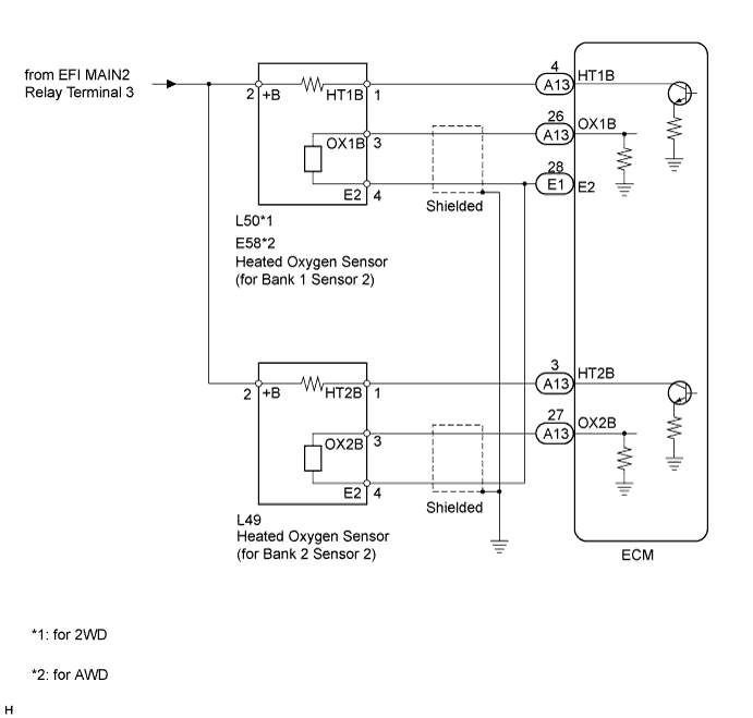
WIRING DIAGRAM
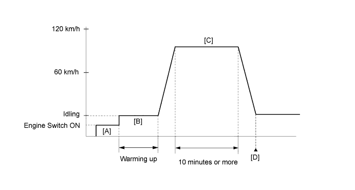
CONFIRMATION DRIVING PATTERN
-
Connect the intelligent tester to the DLC3.
-
Clear the DTCs Click here.
-
Turn the engine switch off.
-
Turn the engine switch on (IG) and turn the tester on (Step "A").
-
Warm-up the engine until the engine coolant temperature is 75°C (167°F) or more (Step "B").
-
With the transmission in 4th gear or more, drive the vehicle at 60 to 120 km/h (37 to 75 mph) for 10 minutes or more (Step "C").
CAUTION:
When performing the confirmation driving pattern, obey all speed limits and traffic laws.
-
Enter the following menus: Powertrain / Engine / Utility / All Readiness.
-
Input DTCs: P0136, P0137, P0138, P0156, P0157 and P0158.
-
Check the DTC judgment result (Step "D").
Tester Display Description NORMAL
-
DTC judgment completed
-
System normal
ABNORMAL
-
DTC judgment completed
-
System abnormal
INCOMPLETE
-
DTC judgment not completed
-
Perform driving pattern after confirming DTC enabling conditions
N/A
-
Unable to perform DTC judgment
-
Number of DTCs which do not fulfill DTC preconditions has reached ECU memory limit
Tech Tips
-
If the judgment result shows NORMAL, the system is normal.
-
If the judgment result shows ABNORMAL, the system has a malfunction.
-
If the judgment result shows INCOMPLETE or N/A, perform steps (Step "C") and (Step "D") again.
-
INSPECTION PROCEDURE
Tech Tips
Intelligent tester only:
Malfunctioning areas can be identified by performing the Control the Injection Volume for A/F Sensor function provided in the Active Test. The Control the Injection Volume for A/F Sensor function can help to determine whether the Air-Fuel Ratio (A/F) sensor, Heated Oxygen (HO2) sensor and other potential trouble areas are malfunctioning.
The following instructions describe how to conduct the Control the Injection Volume for A/F Sensor operation using the intelligent tester.
-
Connect the intelligent tester to the DLC3.
-
Start the engine and turn the tester ON.
-
Warm up the engine at an engine speed of 2500 rpm for approximately 90 seconds.
-
On the tester, enter the following menus: Powertrain / Engine / Active Test / Control the Injection Volume for A/F Sensor.
-
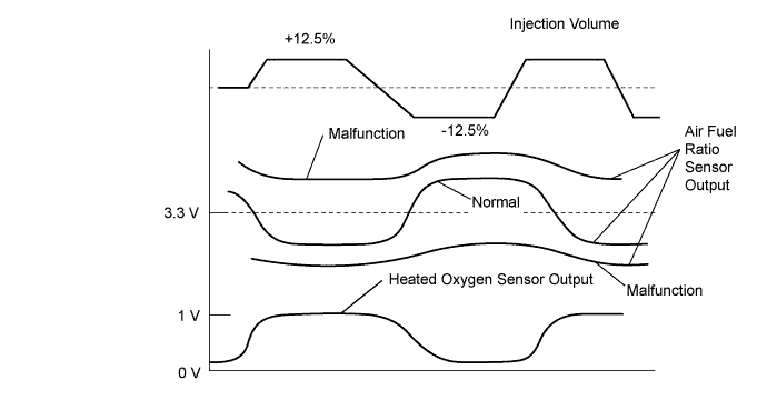
Perform the Active Test operation with the engine in an idling condition (press the RIGHT or LEFT button to change the fuel injection volume).
-
Monitor the output voltages of the A/F and HO2 sensors (AFS voltage B1S1 and O2S B1S2 or AFS voltage B2S1 and O2S B2S2) displayed on the tester.
Tech Tips
-
Change the fuel injection volume within the range of -12.5% to +12.5%.
-
Each sensor reacts in accordance with increases and decreases in the fuel injection volume.
-
If the sensor output voltage does not change (almost no reaction) while performing the Active Test, the sensor may be malfunctioning.
| Tester Display (Sensor) | Injection Volume | Status | Voltage |
|---|---|---|---|
| AFS voltage B1S1 or AFS voltage B2S1 (A/F) |
+12.5% | Rich | Less than 3.0 V |
| AFS voltage B1S1 or AFS voltage B2S1 (A/F) |
-12.5% | Lean | More than 3.35 V |
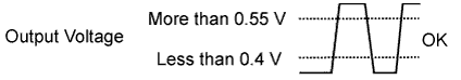
| O2S B1S2 or O2S B2S2 (HO2) |
+12.5% | Rich | More than 0.55 V |
| O2S B1S2 or O2S B2S2 (HO2) |
-12.5% | Lean | Less than 0.4 V |
Note
The Air-Fuel Ratio (A/F) sensor has an output delay of a few seconds and the Heated Oxygen (HO2) sensor has a maximum output delay of approximately 20 seconds.
| Case | A/F Sensor (Sensor 1) Output Voltage | HO2 Sensor (Sensor 2) Output Voltage | Main Suspected Trouble Area |
|---|---|---|---|
| 1 |  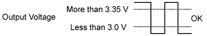 |
 |
- |
| 2 | 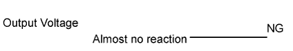 |
|
|
| 3 | |
|
|
| 4 | |
|
|
-
Following the Control the Injection Volume procedure enables technicians to check and graph the voltage outputs of both the A/F and HO2 sensors.
-
To display the graph, enter the following menus: Powertrain / Engine / Active Test / Control the Injection Volume for A/F Sensor / Gas A/F Control / AFS voltage B1S1 and O2S B1S2 or AFS voltage B2S1 and O2S B2S2.
Tech Tips
-
If other DTCs relating to different systems that have terminal E2 as the ground terminal are output simultaneously, terminal E2 may have an open circuit.
-
Read freeze frame data using the intelligent tester. Freeze frame data records the engine condition when malfunctions are detected. When troubleshooting, freeze frame data can help determine if the vehicle was moving or stationary, if the engine was warmed up or not, if the air-fuel ratio was lean or rich, and other data from the time the malfunction occurred.
-
If the OX1B wire from the ECM connector is short-circuited to the +B wire, DTC P0136 will be set.
-
If the OX2B wire from the ECM connector is short-circuited to the +B wire, DTC P0156 will be set.
PROCEDURE
-
READ DTC OUTPUT
-
Connect the intelligent tester to the DLC3.
-
Turn the engine switch on (IG) and turn the tester ON.
-
Enter the following menus: Powertrain / Engine / DTC.
-
Read DTCs.
Result Display (DTC Output) Proceed to P0138 or P0158 A P0137 or P0157 B P0136 or P0156 C DTC P0136, P0137 or P0138 and other DTCs are output D
B 
CHECK EXHAUST GAS LEAK Click here
C
PERFORM ACTIVE TEST USING INTELLIGENT TESTER Click here
D 
GO TO DTC CHART Click here
A 
-
-
READ VALUE USING INTELLIGENT TESTER (OUTPUT VOLTAGE OF HEATED OXYGEN SENSOR)
-
Connect the intelligent tester to the DLC3.
-
Turn the engine switch on (IG) and turn the tester ON.
-
Enter the following menus: Powertrain / Engine / Data List / Gas A/F Control / O2S B1S2 or O2S B2S2.
-
Allow the engine to idle.
-
Read the Heated Oxygen (HO2) sensor output voltage while idling.
Result HO2 Sensor Output Voltages Proceed to 1.0 V or more A Less than 1.0 V B
B
PERFORM ACTIVE TEST USING INTELLIGENT TESTER Click here
A
-
-
INSPECT HEATED OXYGEN SENSOR (CHECK FOR SHORT)
-
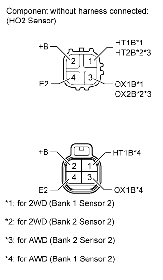
Disconnect the L50, L49 or E58 HO2 sensor connector.
-
Measure the resistance according to the value(s) in the table below.
Standard resistance Tester Connection Condition Specified Condition 2 (+B) - 4 (E2) Always 10 kΩ or higher 2 (+B) - 3 (OX1B) 2 (+B) - 3 (OX2B) Result Result Proceed to OK A NG (for 2WD) B NG (for AWD) C
B
REPLACE HEATED OXYGEN SENSOR Click here
C
REPLACE HEATED OXYGEN SENSOR Click here
A
-
-
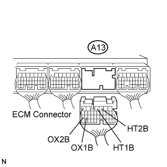
CHECK HARNESS AND CONNECTOR (CHECK FOR SHORT)
-
Turn the engine switch off and wait for 5 minutes.
-
Disconnect the A13 ECM connector.
-
Measure the resistance according to the value(s) in the table below.
Standard resistance Tester Connection Condition Specified Condition A13-4 (HT1B) - A13-26 (OX1B) Always 10 kΩ or higher A13-3 (HT2B) - A13-27 (OX2B) Always 10 kΩ or higher
NG
REPAIR OR REPLACE HARNESS OR CONNECTOR
OK 
REPLACE ECM Click here
-
-
PERFORM ACTIVE TEST USING INTELLIGENT TESTER
-
Connect the intelligent tester to the DLC3.
-
Start the engine and turn the tester ON.
-
Warm up the engine.
-
Enter the following menus: Powertrain / Engine / Active Test / Control the Injection Volume for A/F Sensor.
-
Change the fuel injection volume using the tester, and monitor the voltage output of Air-Fuel Ratio (A/F) and HO2 sensors displayed on the tester.
Tech Tips
-
Change the fuel injection volume within the range of -12.5% and +12.5%.
-
The A/F sensor is displayed as AFS voltage B1S1 or AFS voltage B2S1, and the HO2 sensor is displayed as O2S B1S2 or O2S B2S2 on the intelligent tester.
-
The air fuel ratio sensor has an output delay of a few seconds and the heated oxygen sensor has a maximum output delay of approximately 20 seconds.
-
If the sensor output voltage does not change (almost no reaction) while performing the Active Test, the sensor may be malfunctioning.
Result Tester Display (Sensor) Voltage Variation Proceed to AFS voltage B1S1 (A/F)
AFS voltage B2S1 (A/F)
Alternates between more and less than 3.25 V OK AFS voltage B1S1 (A/F)
AFS voltage B2S1 (A/F)
Remains at more than 3.25 V NG AFS voltage B1S1 (A/F)
AFS voltage B2S1 (A/F)
Remains at less than 3.25 V NG Tech Tips
A normal HO2 sensor voltage (O2S B1S2 or O2S B2S2) reacts in accordance with increases and decreases in fuel injection volumes. When the A/F sensor voltage remains at either less or more than 3.3 V despite the HO2 sensor indicating a normal reaction, the A/F sensor is malfunctioning.
-
NG
REPLACE AIR FUEL RATIO SENSOR Click here
OK
-
-
INSPECT AIR FUEL RATIO SENSOR
Tech Tips
This A/F sensor test is to check the A/F sensor current during the fuel-cut. When the sensor is normal, the sensor current will indicate below 3.0 mA in this test.
-
Clear DTC Click here.
-
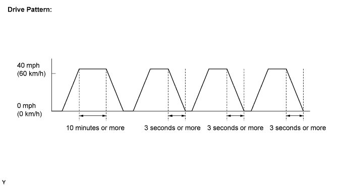
Drive the vehicle using the drive pattern as listed below:
-
Warm up the engine.
-
Drive the vehicle at 40 mph (60 km/h) or more for 10 minutes or more.
-
Stop the vehicle.
-
Accelerate the vehicle until 40 mph (60 km/h) or more and decelerate for 3 seconds or more. Perform this three times.
-
-
Enter the following menus: Powertrain / Engine / Data List / Gas A/F Control / AFS Current B1S1 and AFS Current B2S1.
-
Read the value.
Standard Less than 3.0 mA Tech Tips
If the intelligent tester shows Incomplete again, increase the vehicle speed and use the second gear to decelerate the vehicle.
OK
REPLACE HEATED OXYGEN SENSOR Click here
NG
REPLACE AIR FUEL RATIO SENSOR Click here
-
-
PERFORM ACTIVE TEST USING INTELLIGENT TESTER
-
Connect the intelligent tester to the DLC3.
-
Turn the engine switch on (IG) and turn the tester ON.
-
Start the engine.
-
Warm up the engine.
-
Enter the following menus: Powertrain / Engine / Active Test / Control the Injection Volume for A/F Sensor / Gas A/F Control / O2S B1S2 or O2S B2S2.
-
Change the fuel injection volume using the tester, monitoring the voltage output of the heated oxygen sensor displayed on the tester.
Tech Tips
-
Change the fuel injection volume within the range of -12.5% to +12.5%.
-
The air fuel ratio sensor has an output delay of a few seconds and the heated oxygen sensor has a maximum output delay of approximately 20 seconds.
Standard Fluctuates between 0.4 V or less and 0.55 V or higher. -
NG
CHECK EXHAUST GAS LEAK Click here
OK
-
-
PERFORM ACTIVE TEST USING INTELLIGENT TESTER
-
Connect the intelligent tester to the DLC3.
-
Start the engine and turn the tester ON.
-
Warm up the engine.
-
Enter the following menus: Powertrain / Engine / Active Test / Control the Injection Volume for A/F Sensor.
-
Change the fuel injection volume using the tester, and monitor the voltage output of Air-Fuel Ratio (A/F) and HO2 sensors displayed on the tester.
Tech Tips
-
Change the fuel injection volume within the range of -12.5% and +12.5%.
-
The A/F sensor is displayed as AFS voltage B1S1 or AFS voltage B2S1 and the HO2 sensor is displayed as O2S B1S2 or O2S B2S2 on the intelligent tester.
-
The air fuel ratio sensor has an output delay of a few seconds and the heated oxygen sensor has a maximum output delay of approximately 20 seconds.
-
If the sensor output voltage does not change (almost no reaction) while performing the Active Test, the sensor may be malfunctioning.
Result Tester Display (Sensor) Voltage Variation Proceed to AFS voltage B1S1 (A/F)
AFS voltage B2S1 (A/F)
Alternates between more and less than 3.25 V OK AFS voltage B1S1 (A/F)
AFS voltage B2S1 (A/F)
Remains at more than 3.25 V NG AFS voltage B1S1 (A/F)
AFS voltage B2S1 (A/F)
Remains at less than 3.25 V NG Tech Tips
A normal HO2 sensor voltage (O2S B1S2 or O2S B2S2) reacts in accordance with increases and decreases in fuel injection volumes. When the A/F sensor voltage remains at either less or more than 3.3 V despite the HO2 sensor indicating a normal reaction, the A/F sensor is malfunctioning.
-
NG
REPLACE AIR FUEL RATIO SENSOR Click here
OK
CHECK EXTREMELY RICH OR LEAN ACTUAL AIR FUEL RATIO AND REPAIR CAUSE (INJECTOR, FUEL PRESSURE, GAS LEAKAGE FROM EXHAUST SYSTEM, ETC.)
-
-
CHECK EXHAUST GAS LEAK
-
Check for exhaust gas leaks.
OK No gas leakage.
NG
REPAIR OR REPLACE EXHAUST GAS LEAKAGE POINT Click here
OK
-
-
INSPECT HEATED OXYGEN SENSOR (HEATER RESISTANCE)
-
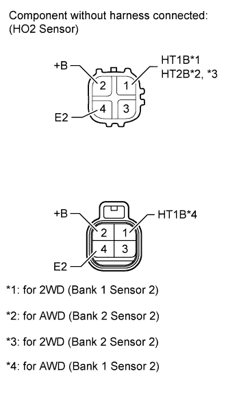
Disconnect the L50, L49 or E58 HO2 sensor connector.
-
Measure the resistance according to the value(s) in the table below.
Standard resistance (Bank 1 Sensor 2) Tester Connection Condition Specified Condition 1 (HT1B) - 2 (+B) 20°C (68°F) 11 to 16 Ω 1 (HT1B) - 4 (E2) Always 10 kΩ or higher Standard resistance (Bank 2 Sensor 2) Tester Connection Condition Specified Condition 1 (HT2B) - 2 (+B) 20°C (68°F) 11 to 16 Ω 1 (HT2B) - 4 (E2) Always 10 kΩ or higher Result Result Proceed to OK A NG (for 2WD) B NG (for AWD) C
B
REPLACE HEATED OXYGEN SENSOR Click here
C
REPLACE HEATED OXYGEN SENSOR Click here
A
-
-
CHECK HARNESS AND CONNECTOR (HEATED OXYGEN SENSOR - ECM)
-
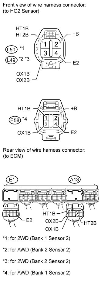
Disconnect the L50, L49 or E55 HO2 sensor connector.
-
Turn the engine switch on (IG).
-
Measure the voltage according to the value(s) in the table below.
Standard voltage Terminal Connection Switch Condition Specified Condition L50-2 (+B) - Body ground Engine switch on (IG) 11 to 14 V E58-2 (+B) - Body ground Engine switch on (IG) 11 to 14 V L49-2 (+B) - Body ground Engine switch on (IG) 11 to 14 V -
Turn the engine switch off.
-
Disconnect the A13 and E1 ECM connectors.
-
Measure the resistance according to the value(s) in the table below.
Standard resistance (Check for open) Terminal Connection Condition Specified Condition L50-1 (HT1B) - A13-4 (HT1B) Always Below 1 Ω L50-3 (OX1B) - A13-26 (OX1B) Always Below 1 Ω L50-4 (E2) - E1-28 (E2) Always Below 1 Ω E58-1 (HT1B) - A13-4 (HT1B) Always Below 1 Ω E58-3 (OX1B) - A13-26 (OX1B) Always Below 1 Ω E55-4 (E2) - E1-28 (E2) Always Below 1 Ω L49-1 (HT2B) - A13-3 (HT2B) Always Below 1 Ω L49-3 (OX2B) - A13-27 (OX2B) Always Below 1 Ω L49-4 (E2) - E1-28 (E2) Always Below 1 Ω Standard resistance (Check for short) Terminal Connection Condition Specified Condition L50-1 (HT1B) or A13-4 (HT1B) - Body ground Always 10 kΩ or higher L50-3 (OX1B) or A13-26 (OX1B) - Body ground Always 10 kΩ or higher L50-4 (E2) or E1-28 (E2) - Body ground Always 10 kΩ or higher E58-1 (HT1B) or A13-4 (HT1B) - Body ground Always 10 kΩ or higher E58-3 (OX1B) or A13-26 (OX1B) - Body ground Always 10 kΩ or higher E58-4 (E2) or E1-28 (E2) - Body ground Always 10 kΩ or higher L49-1 (HT2B) or A13-3 (HT2B) - Body ground Always 10 kΩ or higher L49-3 (OX2B) or A13-27 (OX2B) - Body ground Always 10 kΩ or higher L49-4 (E2) or E1-28 (E2) - Body ground Always 10 kΩ or higher 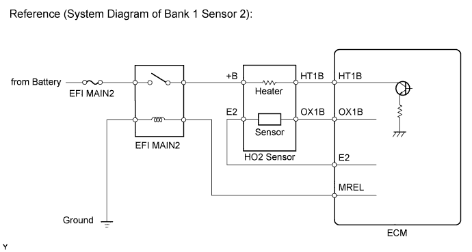
NG
REPAIR OR REPLACE HARNESS OR CONNECTOR
OK
-
-
REPLACE HEATED OXYGEN SENSOR
-
Replace the heated oxygen sensor.
NEXT
-
-
PERFORM CONFIRMATION DRIVING PATTERN
Tech Tips
Refer to the CONFIRMATION DRIVING PATTERN.
NEXT
-
CHECK WHETHER DTC OUTPUT RECURS (DTC P0136, P0137, P0138, P0156, P0157 OR P0158)
-
Connect the intelligent tester to the DLC3.
-
Turn the engine switch on (IG) and turn the tester ON.
-
Enter the following menus: Powertrain / Engine / Utility / All Readiness.
-
Input DTCs: P0136, P0137, P0138, P0156, P0157 and P0158.
-
Check that the DTC monitor is NORMAL. If the DTC monitor is INCOMPLETE, perform the driving pattern again but increase the vehicle speed
Result Display (DTC Output) Proceed to NORMAL
(No DTC output)
A ABNORMAL (for 2WD)
(P0136, P0137, P0138, P0156, P0157 or P0158 detected)
B ABNORMAL (for AWD)
(P0136, P0137, P0138, P0156, P0157 or P0158 detected)
C
B
REPLACE AIR FUEL RATIO SENSOR Click here
C
REPLACE AIR FUEL RATIO SENSOR Click here
A
END
-
-
REPLACE AIR FUEL RATIO SENSOR
-
Replace the air fuel ratio sensor.
NEXT
-
-
PERFORM CONFIRMATION DRIVING PATTERN
Tech Tips
Refer to the CONFIRMATION DRIVING PATTERN.
NEXT
-
CHECK WHETHER DTC OUTPUT RECURS (DTC P0136, P0137, P0138, P0156, P0157 OR P0158)
-
Connect the intelligent tester to the DLC3.
-
Turn the engine switch on (IG) and turn the tester ON.
-
Enter the following menus: Powertrain / Engine / Utility / All Readiness.
-
Input DTCs: P0136, P0137, P0138, P0156, P0157 and P0158.
-
Check that the DTC monitor is NORMAL. If the DTC monitor is INCOMPLETE, perform the driving pattern again but increase the vehicle speed
Result Display (DTC Output) Proceed to NORMAL
(No DTC output)
A ABNORMAL (for 2WD)
(P0136, P0137, P0138, P0156, P0157 or P0158 detected)
B ABNORMAL (for AWD)
(P0136, P0137, P0138, P0156, P0157 or P0158 detected)
C
B
REPLACE HEATED OXYGEN SENSOR Click here
C
REPLACE HEATED OXYGEN SENSOR Click here
A
END
-