SFI SYSTEM, Diagnostic DTC:P1340, P1342, P1343

| DTC Code | DTC Name |
|---|---|
| P1340 | Camshaft Position Sensor "A" (Bank 1 Sensor 2) |
| P1342 | Camshaft Position Sensor "A" Low Input (MRE) |
| P1343 | Camshaft Position Sensor "A" High Input (MRE) |
DESCRIPTION
The camshaft position sensor system consists of a signal plate (installed on the camshaft timing gear RH) and Magnetic Resistance Element (MRE) type cam position sensor. The signal plate has 3 protrusions. When it rotates, the magnetic vector (direction of magnetic field) applied to the camshaft's MRE varies, which causes its resistance to vary. This varying resistance is converted to voltage, and then modified into a rectangular waveform with Hi (approximately 4 V) and Lo (approximately 1 V) outputs. As a result, the G2 signal is output to the ECM. The ECM uses the G2 signal to distinguish between the cylinders and detect the camshaft position.
| DTC No. | DTC Detection Condition | Trouble Area |
|---|---|---|
| P1340 | When either condition below is met:
|
|
| P1342 | Output voltage of camshaft position sensor less than 0.3 V for 4 seconds (1 trip detection logic) |
|
| P1343 | Output voltage of camshaft position sensor more than 4.7 V for 4 seconds (1 trip detection logic) |
|
MONITOR DESCRIPTION
If there is no signal from the camshaft position sensor even though the engine is turning, or if the rotation of the camshaft and the crankshaft is not synchronized, the ECM interprets this as a malfunction of the sensor.
When the sensor output voltage remains less than 0.3 V, or more than 4.7 V for more than 5 seconds, the ECM sets a DTC.
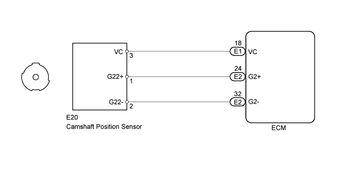
WIRING DIAGRAM
INSPECTION PROCEDURE
-
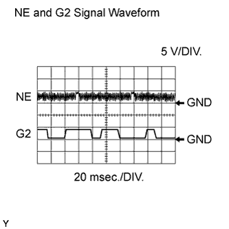
WAVEFORMS (REFERENCE)
-
Camshaft position sensor.
-
Crankshaft position sensor.
Item Content Tester Connection (a) E2-24 (G2+) - E2-32 (G2-)
(b) E1-27 (NE+) - E1-34 (NE-)
Tester Range 5 V/DIV, 20 msec./DIV Condition Idle after engine warmed-up Note
The wavelength becomes shorter as the engine rpm increases.
Tech Tips
Read freeze frame data using the intelligent tester. Freeze frame data records the engine conditions when a malfunction is detected. When troubleshooting, freeze frame data can help determine if the vehicle was running or stopped, if the engine was warmed up or not, if the air-fuel ratio was LEAN or RICH, and other data from the time the malfunction occurred.
-
PROCEDURE
-
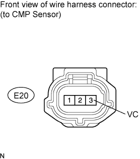
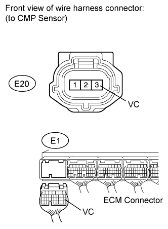
CHECK CAMSHAFT POSITION SENSOR (SENSOR POWER SOURCE)
-
Disconnect the E20 camshaft position sensor connector.
-
Measure the voltage according to the value(s) in the table below.
Standard voltage Tester Connection Switch Condition Specified Condition E20-3 (VC) - Body ground Engine switch on (IG) 4.5 to 5.0 V
NG 
CHECK HARNESS AND CONNECTOR (CAMSHAFT POSITION SENSOR - ECM) Click here
OK 
-
-
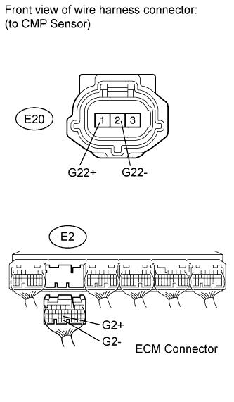
CHECK HARNESS AND CONNECTOR (CAMSHAFT POSITION SENSOR - ECM)
-
Disconnect the E20 camshaft position sensor connector.
-
Disconnect the E2 ECM connector.
-
Measure the resistance according to the value(s) in the table below.
Standard resistance (Check for open) Tester Connection Condition Specified Condition E20-1 (G22+) - E2-24 (G2+) Always Below 1 Ω E20-2 (G22-) - E2-32 (G2-) Always Below 1 Ω Standard resistance (Check for short) Tester Connection Condition Specified Condition E20-1 (G22+) or E2-24 (G2+) - Body ground Always 10 kΩ or higher E20-2 (G22-) or E2-32 (G2-) - Body ground Always 10 kΩ or higher
NG 
REPAIR OR REPLACE HARNESS OR CONNECTOR
OK
-
-
CHECK SENSOR INSTALLATION (CAMSHAFT POSITION SENSOR)
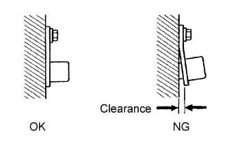
-
Check the sensor installation.
OK Sensor is installed correctly.
NG
SECURELY REINSTALL SENSOR Click here
OK
-
-
INSPECT CAMSHAFT TIMING GEAR ASSEMBLY (BANK 2)
-
Check the teeth of the sensor plate.
OK Sensor plate teeth do not have any cracks or deformation.
NG
REPLACE CAMSHAFT TIMING GEAR ASSEMBLY (BANK 2) Click here
OK
-
-
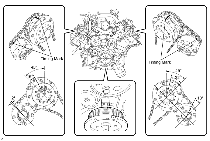
CHECK VALVE TIMING
-
Remove the cylinder head cover bank 1 and bank 2.
-
Turn the crankshaft pulley, and align its groove with the timing mark "0" of the timing chain cover.
-
Rotate the crankshaft pulley and align its notch to timing mark 0 of the timing chain cover. Check that the timing marks of the camshaft timing gears and camshaft timing exhaust gears are at the positions shown in the illustration.
OK Timing marks on camshaft timing gears are aligned as shown in the illustration. -
Reinstall the cylinder head cover.
NG
ADJUST VALVE TIMING Click here
OK
-
-
REPLACE CAMSHAFT POSITION SENSOR
-
Replace the camshaft position sensor Click here.
NEXT
-
-
CHECK WHETHER DTC OUTPUT RECURS (P1340, P1342 AND/OR P1343)
-
Connect the intelligent tester to the DLC3.
-
Turn the engine switch on (IG).
-
Turn the tester ON.
-
Clear DTCs Click here.
-
Start the engine.
-
Enter the following menus: Powertrain / Engine / DTC / Pending Codes.
-
Read DTCs.
Result Display (DTC Output) Proceed to No output A P1340, P1342 and/or P1343 B Tech Tips
If the engine does not start, replace the ECM.
B
REPLACE ECM Click here
A 
END
-
-
CHECK HARNESS AND CONNECTOR (CAMSHAFT POSITION SENSOR - ECM)
-
Disconnect the E20 camshaft position sensor connector.
-
Disconnect the E1 ECM connector.
-
Measure the resistance according to the value(s) in the table below.
Standard resistance (Check for open) Tester Connection Condition Specified Condition E20-3 (VC) - E1-18 (VC) Always Below 1 Ω Standard resistance (Check for short) Tester Connection Condition Specified Condition E20-3 (VC) or E1-18 (VC) - Body ground Always 10 kΩ or higher
NG
REPAIR OR REPLACE HARNESS OR CONNECTOR
OK
REPLACE ECM Click here
-