ENGINE IMMOBILISER SYSTEM, Diagnostic DTC:B2799

| DTC Code | DTC Name |
|---|---|
| B2799 | Engine Immobiliser System Malfunction |
DESCRIPTION
This DTC is output when one of the following occurs: 1) the ECM detected errors in its own communications with the immobiliser code ECU; 2) the ECM detects errors in the communication lines; or 3) the ECU communication ID between the immobiliser code ECU and ECM is different and an engine start is attempted. Before troubleshooting for this DTC, make sure no certification ECU DTCs are present. If present, troubleshoot the certification ECU DTCs first.
| DTC Code | DTC Detection Condition | Trouble Area |
|---|---|---|
| B2799 | Either condition is met (1 trip detection logic*1):
|
|
-
*1: Only output while a malfunction is present.
-
*2: w/ Blocking System
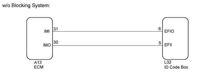
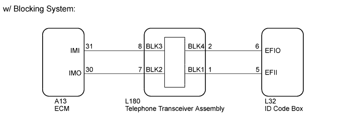
WIRING DIAGRAM
INSPECTION PROCEDURE
Note
-
The fixed 12 V power source voltage in the ECM is output through a resistance from terminal IMI. The ID code box grounds or does not ground this power source voltage accordingly.
-
The fixed 12 V power source voltage in the ID code box is output through a resistance from terminal EFII. The ECM grounds or does not ground this power source voltage accordingly.
-
When replacing the ID code box, ECM or telephone transceiver assembly (w/ Blocking System), refer to the Service Bulletin.
-
After performing repairs, perform the operation that fulfills the DTC output confirmation operation, and then confirm that no DTCs are output again.
Tech Tips
-
When DTC B1587 and B2799 are output simultaneously, perform troubleshooting for DTC B2799 first.
-
After troubleshooting for this DTC, make sure B2799 is not output. If output, troubleshoot the blocking system DTCs next.
w/ Blocking System:
PROCEDURE
-
CLEAR DTC
-
Clear the DTCs Click here.
NEXT 
-
-
CHECK FOR DTC
-
Check for DTCs Click here.
OK DTC B2799 is not output. Result Result Proceed to OK A NG (w/ Blocking System) B NG (w/o Blocking System) C
B 
CHECK BLOCKING SYSTEM Click here
C
REREGISTER ECU COMMUNICATION ID Click here
A 
USE SIMULATION METHOD TO CHECK Click here
-
-
CHECK BLOCKING SYSTEM
-
Check the blocking system setting.
Tech Tips
-
Check with the customer's contacted service provider to determine whether the blocking system is set.
-
Request that the customer have the service provider unset the blocking system.
Result Result Proceed to Blocking system is unset. A Blocking system is set. B -
B 
UNSET BLOCKING SYSTEM
A
-
-
REREGISTER ECU COMMUNICATION ID
-
Reregister the ECU - ECM communication ID (Refer to Service Bulletin).
NEXT
-
-
CLEAR DTC
-
Clear the DTCs Click here.
NEXT
-
-
CHECK FOR DTC
-
Check for DTCs Click here.
OK DTC B2799 is not output.
NG
CHECK CONNECTION OF CONNECTOR Click here
OK
END (ECU COMMUNICATION ID IS NOT REGISTERED CORRECTLY)
-
-
CHECK CONNECTION OF CONNECTOR
-
Turn the engine switch off.
-
Check that the connectors are properly connected to the ECM and ID code box.
OK Connectors are properly connected.
NG
CONNECT CONNECTOR CORRECTLY
OK
-
-
CHECK HARNESS AND CONNECTOR (SFI COMMUNICATION LINE)
-
Disconnect the L32 ID code box connector.
-
Disconnect the A13 ECM connector.
-
w/ Blocking System:
-
Disconnect the L180 telephone transceiver assembly connector.
-
-
Measure the resistance according to the value(s) in the table below.
Standard Resistance w/o Blocking System Tester Connection Condition Specified Condition L32-6 (EFIO) - A13-31 (IMI) Always Below 1 Ω L32-5 (EFII) - A13-30 (IMO) Always Below 1 Ω L32-6 (EFIO) - Body ground Always 10 kΩ or higher L32-5 (EFII) - Body ground Always 10 kΩ or higher w/ Blocking System Tester Connection Condition Specified Condition L32-6 (EFIO) - L180-2 (BLK4) Always Below 1 Ω L32-5 (EFII) - L180-1 (BLK1) Always Below 1 Ω L180-8 (BLK3) - A13-31 (IMI) Always Below 1 Ω L180-7 (BLK2) - A13-30 (IMO) Always Below 1 Ω L32-6 (EFIO) - Body ground Always 10 kΩ or higher L32-5 (EFII) - Body ground Always 10 kΩ or higher A13-30 (IMO) - Body ground Always 10 kΩ or higher A13-31 (IMI) - Body ground Always 10 kΩ or higher -
Measure the voltage according to the value(s) in the table below.
Standard Voltage w/o Blocking System Tester Connection Condition Specified Condition L32-6 (EFIO) - Body ground Always Below 1 V L32-5 (EFII) - Body ground Always Below 1 V w/ Blocking System Tester Connection Condition Specified Condition L32-6 (EFIO) - Body ground Always Below 1 V L32-5 (EFII) - Body ground Always Below 1 V A13-30 (IMO) - Body ground Always Below 1 V A13-31 (IMI) - Body ground Always Below 1 V
NG
REPAIR OR REPLACE HARNESS OR CONNECTOR
OK
-
-
REPLACE ECM
-
Temporarily replace the ECM with a new one.
-
for 1UR-FSE: Click here
-
for 1UR-FE: Click here
-
NEXT
-
-
REREGISTER ECU COMMUNICATION ID
-
Reregister the ECU - ECM communication ID (Refer to Service Bulletin).
NEXT
-
-
CLEAR DTC
-
Clear the DTCs Click here.
NEXT
-
-
CHECK FOR DTC
-
Check for DTCs Click here.
OK DTC B2799 is not output. Result Result Proceed to OK A NG (w/o Blocking System) B NG (w/ Blocking System) C
B
REPLACE ID CODE BOX
C
REPLACE ID CODE BOX Click here
A
END (ECM IS DEFECTIVE)
-
-
REPLACE ID CODE BOX
-
Temporarily replace the ID code box with a new one (Refer to Service Bulletin).
NEXT
-
-
REGISTER ECU COMMUNICATION ID
-
Reregister the ECU - ECM communication ID (Refer to Service Bulletin).
NEXT
-
-
CLEAR DTC
-
Clear the DTCs Click here.
NEXT
-
-
CHECK FOR DTC
-
Check for DTCs Click here.
OK DTC B2799 is not output.
NG
REPLACE TELEPHONE TRANSCEIVER ASSEMBLY
OK
END (ID CODE BOX IS DEFECTIVE)
-