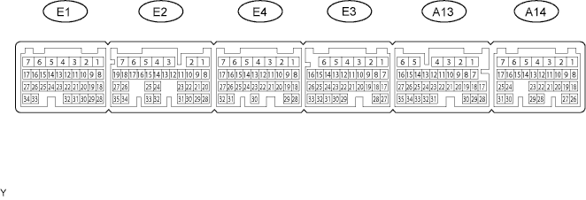
CRUISE CONTROL SYSTEM TERMINALS OF ECM

-
CHECK ECM
-
Disconnect the A13, A14 and E3 ECM connectors.
-
Measure the voltage and resistance according to the value(s) in the table below.
Terminal No (Symbols) Wiring Color Terminal Description Condition Specified Condition A14-12 (ST1-) - Body ground V - Body ground Stop light switch signal Engine switch on (IG),
release brake pedal
11 to 14 V A14-12 (ST1-) - Body ground V - Body ground Stop light switch signal Engine switch on (IG),
depress brake pedal
Below 1 V A14-13 (STP) - Body ground L - Body ground Stop light switch signal Depress brake pedal 11 to 14 V A14-13 (STP) - Body ground L - Body ground Stop light switch signal Release brake pedal Below 1 V A14-8 (IGSW) - Body ground R - Body ground IGSW power supply Engine switch on (IG) 11 to 14 V A14-8 (IGSW) - Body ground R - Body ground IGSW power supply Engine switch off Below 1 V A14-7 (BATT) - Body ground B- Body ground BATT power supply Always 11 to 14 V A13-2 (+B) - Body ground B-W - Body ground*1
B - Body ground*2
+B power supply Engine switch on (IG) 11 to 14 V A13-2 (+B) - Body ground B-W - Body ground*1
B - Body ground*2
+B power supply Engine switch off Below 1 V E3-1 (E1) - Body ground W-B - Body ground Body ground Always Below 1 Ω A13-15 (CCS) - Body ground V - Body ground Cruise control switch signal Cruise control switch ON Below 1 Ω A13-15 (CCS) - Body ground V - Body ground Cruise control switch signal Cruise control switch OFF 10 kΩ or higher A13-15 (CCS) - Body ground V - Body ground Cruise control switch signal +/RES switch is hold ON 235 to 245 Ω A13-15 (CCS) - Body ground V - Body ground Cruise control switch signal -/SET switch is hold ON 620 to 640 Ω A13-15 (CCS) - Body ground V - Body ground Cruise control switch signal CANCEL switch is hold ON 1510 to 1570 Ω E3-14 (D) - Body ground G-Y - Body ground Park / neutral position switch signal Engine switch on (IG),
shift lever D
11 to 14 V E3-14 (D) - Body ground G-Y - Body ground Park / neutral position switch signal Engine switch on (IG),
shift lever except D
Below 1 V E3-13 (N) - Body ground G-R - Body ground Park / neutral position switch signal Engine switch on (IG),
shift lever N
11 to 14 V E3-13 (N) - Body ground G-R - Body ground Park / neutral position switch signal Engine switch on (IG),
shift lever except N
Below 1 V E3-11 (R) - Body ground G - Body ground Park / neutral position switch signal Engine switch on (IG),
shift lever R
11 to 14 V E3-11 (R) - Body ground G - Body ground Park / neutral position switch signal Engine switch on (IG),
shift lever except R
Below 1 V E3-12 (P) - Body ground W - Body ground Park / neutral position switch signal Engine switch on (IG),
shift lever P
11 to 14 V E3-12 (P) - Body ground W - Body ground Park / neutral position switch signal Engine switch on (IG),
shift lever except P
Below 1 V Tech Tips
*1: for 1UZ-FSE (for LHD), 1UZ-FE
*2: for 1UZ-FSE (for RHD)
If the result is not as specified, there may be a malfunction on the wire harness side.
-