BLOCKING SYSTEM Engine does not Start
DESCRIPTION
If the engine does not start and no DTCs are output, the following conditions may apply:
-
There is a short circuit between the telephone transceiver assembly and the ID code box (immobiliser code ECU).
-
The blocking system is set.
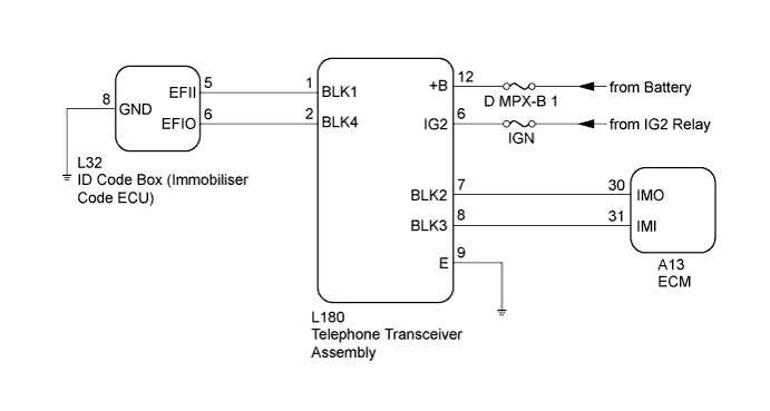
WIRING DIAGRAM
INSPECTION PROCEDURE
Note
-
Before troubleshooting this symptom, make sure no immobiliser system DTCs or blocking system DTCs are present. If present, troubleshoot the immobiliser system DTCs or blocking system DTCs first.
-
When replacing the telephone transceiver assembly and ID code box (immobiliser code ECU), refer to the Service Bulletin.
-
When the telephone transceiver assembly is replaced, it is necessary to set the contract mode.
-
Inspect the fuses for circuits related to this system before performing the following inspection procedure.
PROCEDURE
-
CHECK BLOCKING SYSTEM (SETTING)
-
Check the blocking system setting.
Tech Tips
Check with the customer's contracted service provider to determine whether the blocking system is set.
Result Result Proceed to Blocking system is unset. A Blocking system is set. B
B 
UNSET BLOCKING SYSTEM
A 
-
-
CHECK HARNESS AND CONNECTOR (TELEPHONE TRANSCEIVER ASSEMBLY - ID CODE BOX [IMMOBILISER CODE ECU])
-
Disconnect the L180 telephone transceiver assembly connector.
-
Disconnect the L32 ID code box (immobiliser code ECU) connector.
-
Measure the resistance according to the value(s) in the table below.
Standard Resistance Tester Connection Condition Specified Condition L180-1 (BLK1) - L32-5 (EFII) Always Below 1 Ω L180-2 (BLK4) - L32-6 (EFIO) Always Below 1 Ω
NG
REPAIR OR REPLACE HARNESS OR CONNECTOR
OK
-
-
CHECK ID CODE BOX (IMMOBILISER CODE ECU) (OUTPUT)
-
Reconnect the L180 telephone transceiver assembly connector.
-
Reconnect the L32 ID code box (immobiliser code ECU) connector.
-
Using an oscilloscope, check the waveform.
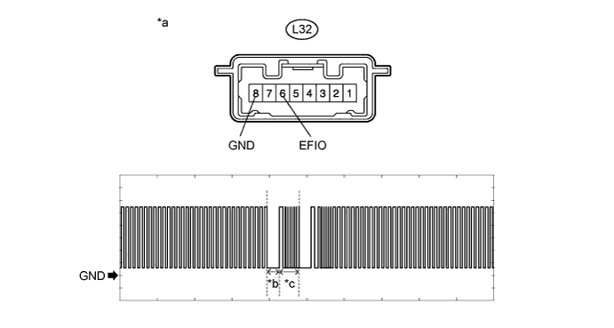
Text in Illustration *a Component with harness connected
(ID Code Box [Immobiliser Code ECU])
*b Approximately 160 ms. *c Approximately 270 ms. - - Measurement Condition Item Content Tester Connection L32-6 (EFIO) - L32-8 (GND) Tool Setting 2 V/DIV., 500 ms./DIV. Condition Within 3 seconds of engine start or within 3 seconds of engine switch turned on (IG) after battery cable disconnected and reconnected Tech Tips
The waveform shown in the illustration is an example for reference only. Noise, chattering, etc. are not shown.
OK The waveform is output normally (refer to illustration). Result Result Proceed to NG (stuck low) A NG (stuck high) B OK C
B
REPLACE TELEPHONE TRANSCEIVER ASSEMBLY
C 
REGISTER ECU COMMUNICATION ID Click here
A
-
-
REPLACE ID CODE BOX (IMMOBILISER CODE ECU)
-
Temporarily replace the ID code box (immobiliser code ECU) with a new one.
Tech Tips
Refer to the Service Bulletin.
NEXT
-
-
PERFORM REGISTRATION
-
Perform the registration.
Tech Tips
Refer to the Service Bulletin.
NEXT
-
-
CHECK WHETHER ENGINE STARTS
-
Check that the engine starts normally.
OK Engine starts normally.
NG
REPLACE TELEPHONE TRANSCEIVER ASSEMBLY
OK 
END (ID CODE BOX [IMMOBILISER CODE ECU] WAS DEFECTIVE)
-
-
REGISTER ECU COMMUNICATION ID
-
Register the ECU communication ID between the ECM and ID code box (immobiliser code ECU).
Tech Tips
Refer to the Service Bulletin.
NEXT
-
-
CHECK WHETHER ENGINE STARTS
-
Check that the engine starts normally.
OK Engine starts normally.
NG
REPLACE TELEPHONE TRANSCEIVER ASSEMBLY
OK
END (ECU COMMUNICATION ID WAS NOT REGISTERED CORRECTLY)
-