BLOCKING SYSTEM TERMINALS OF ECU
-
CHECK TELEPHONE TRANSCEIVER ASSEMBLY
-
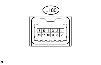
Disconnect the L180 telephone transceiver assembly connector.
-
Measure the resistance and voltage according to the value(s) in the table below.
Terminal No. (Symbol) Wiring Color Terminal Description Condition Specified Condition L180-6 (IG2) - L180-9 (E) R - W-B Ignition power supply Engine switch on (IG) 9 to 16 V L180-12 (+B) - L180-9 (E) W - W-B +B power supply Always 9 to 16 V L180-9 (E) - Body ground W-B - Body ground Ground Always Below 1 Ω
-
If the result is not as specified, there may be a malfunction on the wire harness side.
-
-
Reconnect the L180 telephone transceiver assembly connector.
-
Measure the voltage according to the value(s) in the table below.
Terminal No. (Symbol) Wiring Color Terminal Description Condition Specified Condition L180-1 (BLK1) - L180-9 (E) Y - W-B ID code box (immobiliser code ECU) communication input Engine switch off 11 to 14 V L180-1 (BLK1) - L180-9 (E) Y - W-B ID code box (immobiliser code ECU) communication input Within 3 seconds of engine start or within 3 seconds of engine switch turned on (IG) after battery cable disconnected and reconnected Pulse generation
(See waveform 1)
L180-2 (BLK4) - L180-9 (E) GR - W-B ID code box (immobiliser code ECU) communication output Engine switch off Below 1 V L180-2 (BLK4) - L180-9 (E) GR - W-B ID code box (immobiliser code ECU) communication output Within 3 seconds of engine start or within 3 seconds of engine switch turned on (IG) after battery cable disconnected and reconnected Pulse generation
(See waveform 2)
L180-7 (BLK2) - L180-9 (E) B - W-B ECM communication output Engine switch off Below 1 V L180-7 (BLK2) - L180-9 (E) B - W-B ECM communication output Within 3 seconds of engine start or within 3 seconds of engine switch turned on (IG) after battery cable disconnected and reconnected Pulse generation
(See waveform 1)
L180-8 (BLK3) - L180-9 (E) G - W-B ECM communication input Engine switch off Below 1 V L180-8 (BLK3) - L180-9 (E) G - W-B ECM communication input Within 3 seconds of engine start or within 3 seconds of engine switch turned on (IG) after battery cable disconnected and reconnected Pulse generation
(See waveform 2)
-
Inspect using an oscilloscope.
Note
The waveform shown in the illustration is an example for reference only. Noise, chattering, etc. are not shown.
-
Waveform 1 (Reference)
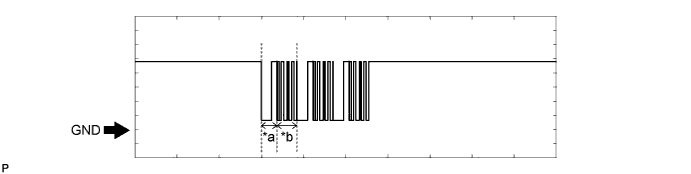
Text in Illustration *a Approximately 160 ms. *b Approximately 270 ms. Measurement Condition Item Content Tester Connection
-
L180-1 (BLK1) - L180-9 (E)
-
L180-7 (BLK2) - L180-9 (E)
Tool Setting 2 V/DIV., 500 ms./DIV. Condition Within 3 seconds of engine start or within 3 seconds of engine switch turned on (IG) after battery cable disconnected and reconnected -
-
Waveform 2 (Reference)
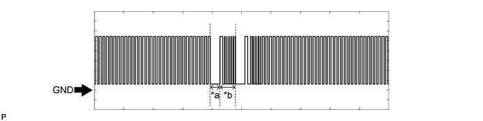
Text in Illustration *a Approximately 160 ms. *b Approximately 270 ms. Measurement Condition Item Content Tester Connection
-
L180-2 (BLK4) - L180-9 (E)
-
L180-8 (BLK3) - L180-9 (E)
Tool Setting 2 V/DIV., 500 ms./DIV. Condition Within 3 seconds of engine start or within 3 seconds of engine switch turned on (IG) after battery cable disconnected and reconnected -
-
-
-
CHECK ID CODE BOX (IMMOBILISER CODE ECU)
-
Disconnect the L32 ID code box (immobiliser code ECU) connector.

-
Measure the resistance and voltage according to the value(s) in the table below.
Terminal No. (Symbol) Wiring Color Terminal Description Condition Specified Condition L32-1 (+B) - L32-8 (GND) L - W-B +B power supply Always 11 to 14 V L32-8 (GND) - Body ground W-B - Body ground Ground Always Below 1 Ω
-
If the result is not as specified, there may be a malfunction in the wire harness.
-
-
Reconnect the L32 ID code box (immobiliser code ECU) connector.
-
Measure the voltage according to the value(s) in the table below.
Terminal No. (Symbol) Wiring Color Terminal Description Condition Specified Condition L32-5 (EFII) - L32-8 (GND) Y - W-B ECM input signal Engine switch off 11 to 14 V L32-5 (EFII) - L32-8 (GND) Y - W-B ECM input signal Within 3 seconds after starter operates and initial combustion occurs, or within 3 seconds after engine switch first turned on (IG) after battery disconnected and connected Pulse generation
(See waveform 1)
L32-6 (EFIO) - L32-8 (GND) GR - W-B ECM output signal Engine switch off Below 1 V L32-6 (EFIO) - L32-8 (GND) GR - W-B ECM output signal Within 3 seconds after starter operates and initial combustion occurs, or within 3 seconds after engine switch first turned on (IG) after battery disconnected and connected Pulse generation
(See waveform 2)
-
Inspect using an oscilloscope.
-
Waveform 1 (Reference)
Text in Illustration *a Approximately 160 ms. *b Approximately 270 ms. Item Content Tester Connection L32-5 (EFII) - L32-8 (GND) Tool Setting 5 V/DIV., 500 ms./DIV. Condition Within 3 seconds after starter operates and initial combustion occurs, or within 3 seconds after engine switch first turned on (IG) after battery disconnected and connected -
Waveform 2 (Reference)
Text in Illustration *a Approximately 160 ms. *b Approximately 270 ms. Item Content Tester Connection L32-6 (EFIO) - L32-8 (GND) Tool Setting 10 V/DIV., 100 ms./DIV. Condition Within 3 seconds after starter operates and initial combustion occurs, or within 3 seconds after engine switch first turned on (IG) after battery disconnected and connected
-
-
-
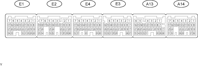
CHECK ECM
-
Measure the resistance and voltage according to the value(s) in the table below.
Terminal No. (Symbols) Wiring Color Terminal Description Condition Specified Condition E3-1 (E1) - Body ground W-B - Body ground Ground Always Below 1 Ω E2-2 (E01) - Body ground W-B - Body ground Ground Always Below 1 Ω E2-1 (E02) - Body ground W-B - Body ground Ground Always Below 1 Ω A13-5 (E03) - Body ground W-B - Body ground Ground Always Below 1 Ω E3-4 (E04) - Body ground W-B - Body ground Ground Always Below 1 Ω A14-1 (EC) - Body ground W-B - Body ground Ground Always Below 1 Ω E2-5 (ME01) - Body ground W-B - Body ground Ground Always Below 1 Ω A14-7 (BATT) - E3-1 (E1) B - W-B Battery (for measuring battery voltage and for ECM memory) Always 9 to 14 V A13-2 (+B) - E3-1 (E1) B - W-B Power source of ECM Engine switch off Below 1 V Engine switch on (IG) 9 to 14 V A13-1 (+B2) - E3-7 (E1) B - W-B Power source of ECM Engine switch off Below 1 V Engine switch on (IG) 9 to 14 V A13-31 (IMI) - E3-1 (E1) L - W-B ID code box input signal Engine switch off Below 1 V Within 3 seconds after starter operates and initial combustion occurs, or within 3 seconds after engine switch first turned on (IG) after battery disconnected and connected Pulse generation (See waveform 1) A13-30 (IMO) - E3-1 (E1) B - W-B ID code box output signal Engine switch off Below 1 V Within 3 seconds after starter operates and initial combustion occurs, or within 3 seconds after engine switch first turned on (IG) after battery disconnected and connected Pulse generation (See waveform 2) -
Inspect using an oscilloscope.
Note
The waveform shown in the illustration is an example for reference only. Noise, chattering, etc. are not shown.
-
Waveform 1 (Reference)
Text in Illustration *a Approximately 160 ms. *b Approximately 270 ms. Measurement Condition Item Content Tester Connection A13-30 (IMO) - E3-1 (E1) Tool Setting 2 V/DIV., 500 ms./DIV. Condition Within 3 seconds of engine start or within 3 seconds of engine switch turned on (IG) after battery cable disconnected and reconnected -
Waveform 2 (Reference)
Text in Illustration *a Approximately 160 ms. *b Approximately 270 ms. Measurement Condition Item Content Tester Connection A13-31 (IMI) - E3-1 (E1) Tool Setting 2 V/DIV., 500 ms./DIV. Condition Within 3 seconds of engine start or within 3 seconds of engine switch turned on (IG) after battery cable disconnected and reconnected
-
-