SEAT BELT WARNING SYSTEM TERMINALS OF ECU

-
CHECK NO. 1 METER ECU SUB-ASSEMBLY
-
Disconnect the L10 No. 1 meter ECU sub-assembly connector.

-
Measure the resistance and voltage according to the value(s) in the table below.
Tester Connection Wiring Color Terminal Description Condition Specified Condition L10-14 (IG2) - Body ground L - Body ground Ignition power supply
(IG signal)
Engine switch off Below 1 V Engine switch on (IG) 11 to 14 V L10-13 (B) - Body ground P - Body ground Battery power supply Always 11 to 14 V L10-18 (ES) - Body ground BR - Body ground Ground Always Below 1 Ω -
Reconnect the L10 No. 1 meter ECU sub-assembly connector.
-
Measure the voltage according to the value(s) in the table below.
Tester Connection Wiring Color Terminal Description Condition Specified Condition L10-24 (EPB) - Body ground L - Body ground Parking brake switch signal Engine switch on (IG), parking brake switch off 11 to 14 V Engine switch on (IG), parking brake switch on Below 1.5 V
-
-
CHECK CENTER AIRBAG SENSOR ASSEMBLY
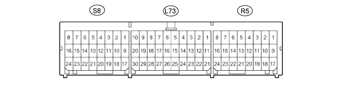
Terminal No. Terminal Symbol Destination S8-10*1 LBE+ Front seat inner belt assembly LH R5-15*1 RBE+ Front seat inner belt assembly RH R5-16*1 FSR+ Occupant detection sensor R5-22*1 FSR- Occupant detection sensor R5-15*2 RBE+ Front seat inner belt assembly RH S8-9*2 FSL+ Occupant detection sensor S8-10*2 LBE+ Front seat inner belt assembly LH S8-19*2 FSL- Occupant detection sensor
-
*1: for LHD
-
*2: for RHD
-