POWER SHOULDER BELT ANCHORAGE SYSTEM TERMINALS OF ECU

-
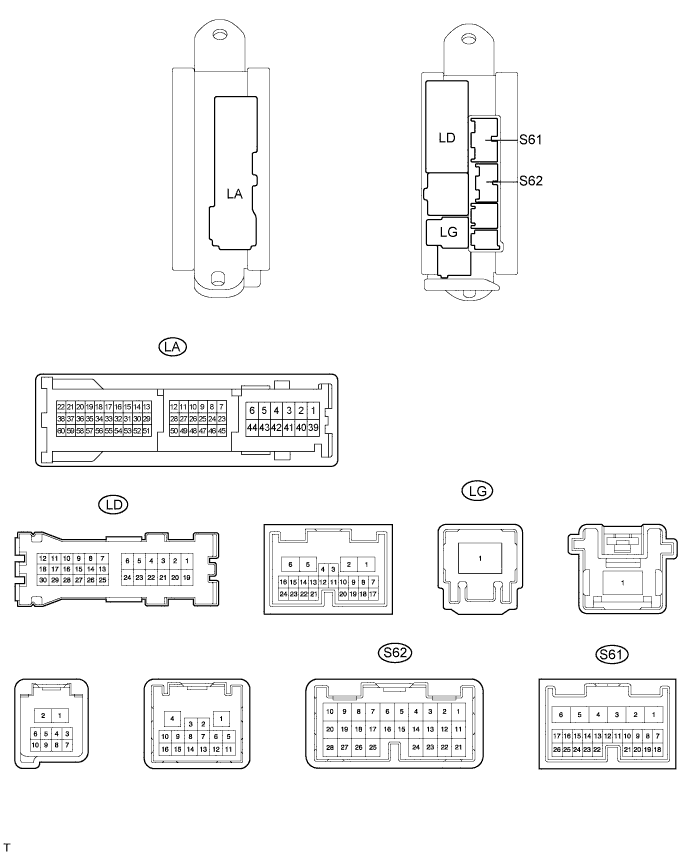
CHECK LUGGAGE ROOM JUNCTION BLOCK (REAR JUNCTION BLOCK ECU)
-
Disconnect the LA, LD and LG ECU connectors.
-
Measure the voltage and resistance according to the value(s) in the table below.
Terminal No. (Symbols) Wiring Color Terminal Description Condition Specified Condition LD-4 (MPXB) - Body ground R - Body ground Battery (ECU power source) Always 11 to 14 V LG-1 (BANC) - Body ground W - Body ground Battery (ECU power source) Always 11 to 14 V LA-43 (PGND) - Body ground W-B - Body ground Ground Always Below 1 Ω If the result is not as specified, there may be a malfunction on the wire harness side.
-
Reconnect the LA, LD and LG ECU connectors.
-
Measure the voltage and resistance according to the value(s) in the table below.
Terminal No. (Symbols) Wiring Color Terminal Description Condition Specified Condition S61-8 (DBM-) - Body ground Y - Body ground Seat belt anchor motor power Shoulder belt anchorage switch off Below 1 V Shoulder belt anchorage switch down 11 to 14 V S61-10 (DBM+) - Body ground L - Body ground Seat belt anchor motor power Shoulder belt anchorage switch off Below 1 V Shoulder belt anchorage switch up 11 to 14 V S61-13 (E) - Body ground W - Body ground Ground Always Below 1 Ω S61-14 (BES) - Body ground R - Body ground Seat belt anchor motor power Seat belt anchor motor drive Alternating between approximately 8 V and below 1 V Seat belt anchor motor stop Below 1 V S61-15 (VC) - Body ground Y - Body ground Battery (seat belt anchor power) Always 11 to 14 V S62-3 (PVC) - Body ground Y - Body ground Battery (seat belt anchor power) Always 11 to 14 V S62-4 (PBES) - Body ground R - Body ground Seat belt anchor motor power Seat belt anchor motor drive Alternating between approximately 8 V and below 1 V Seat belt anchor motor stop Below 1 V S62-27 (PSSE) - Body ground LG - Body ground Ground Always Below 1 Ω S62-22 (PBM+) - Body ground V - Body ground Seat belt anchor motor power Shoulder belt anchorage switch off Below 1 V Shoulder belt anchorage switch up 11 to 14 V S62-23 (PBM-) - Body ground L - Body ground Seat belt anchor motor power Shoulder belt anchorage switch off Below 1 V Shoulder belt anchorage switch down 11 to 14 V If the result is not as specified, the ECU or switch may have a malfunction.
-
-
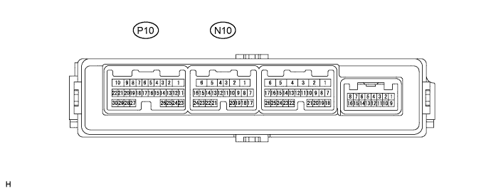
CHECK FRONT DOOR ECU LH
-
Disconnect the N10 and P10 ECU connectors.
-
Measure the voltage and resistance according to the value(s) in the table below.
Terminal No. (Symbols) Wiring Color Terminal Description Condition Specified Condition N10-1 (GND) - Body ground W-B - Body ground Ground Always Below 1 Ω P10-29 (MSWE) - N10-1 (GND) V - W-B Ground Always Below 1 Ω *P10-28 (DSE) - N10-1 (GND) O - W-B Ground Always Below 1 Ω P10-28 (PSE) - N10-1 (GND) O - W-B Ground Always Below 1 Ω N10-11 (CPUB) - N10-1 (GND) B - W-B Battery (ECU power source) Always 11 to 14 V N10-6 (BDR) - N10-1 (GND) O - W-B Battery (ECU power source) Always 11 to 14 V N10-3 (SIG) - N10-1 (GND) L - W-B Engine switch signal Engine switch on (IG) 11 to 14 V P10-16 (MM) - N10-1 (GND) BE - W-B Memory switch signal Memory switch set off 10 kΩ or higher Memory switch set on Below 1 Ω P10-13 (M1) - N10-1 (GND) R - W-B Memory switch signal Memory switch M1 off 10 kΩ or higher Memory switch M1 on Below 1 Ω P10-14 (M2) - N10-1 (GND) B - W-B Memory switch signal Memory switch M2 off 10 kΩ or higher Memory switch M2 on Below 1 Ω P10-15 (M3) - N10-1 (GND) Y - W-B Memory switch signal Memory switch M3 off 10 kΩ or higher Memory switch M3 on Below 1 Ω *P10-17 (DSDN) - N10-1 (GND) R - W-B Seat belt anchorage switch signal Anchorage switch down off 10 kΩ or higher Anchorage switch down on Below 1 Ω P10-17 (PSDN) - N10-1 (GND) R - W-B Seat belt anchorage switch signal Anchorage switch down off 10 kΩ or higher Anchorage switch down on Below 1 Ω *P10-18 (DSUP) - N10-1 (GND) B - W-B Seat belt anchorage switch signal Seat belt anchorage switch up off 10 kΩ or higher Seat belt anchorage switch UP on Below 1 Ω P10-18 (PSUP) - N10-1 (GND) B - W-B Seat belt anchorage switch signal Seat belt anchorage switch up off 10 kΩ or higher Seat belt anchorage switch UP on 10 kΩ or higher Tech Tips
*: for LHD
If the result is not as specified, there may be a malfunction on the wire harness side.
-
Reconnect the N10 and P10 ECU connectors.
-
Measure the voltage according to the value(s) in the table below.
Terminal No. (Symbols) Wiring Color Terminal Description Condition Specified Condition P10-16 (MM) - N10-1 (GND) BE - W-B Memory switch signal Memory switch set off 11 to 14 V Memory switch set on Below 1 V P10-13 (M1) - N10-1 (GND) R - W-B Memory switch signal Memory switch M1 off 11 to 14 V Memory switch M1 on Below 1 V P10-14 (M2) - N10-1 (GND) B - W-B Memory switch signal Memory switch M2 off 11 to 14 V Memory switch M2 on Below 1 V P10-15 (M3) - N10-1 (GND) Y - W-B Memory switch signal Memory switch M3 off 11 to 14 V Memory switch M3 on Below 1 V *P10-17 (DSDN) - N10-1 (GND) R - W-B Seat belt anchorage switch signal Anchorage switch down off 11 to 14 V Anchorage switch down on Below 1 V P10-17 (PSDN) - N10-1 (GND) R - W-B Seat belt anchorage switch signal Anchorage switch down off 11 to 14 V Anchorage switch down on Below 1 V *P10-18 (DSUP) - N10-1 (GND) B - W-B Seat belt anchorage switch signal Seat belt anchorage switch up off 11 to 14 V Seat belt anchorage switch up on Below 1 V P10-18 (PSUP) - N10-1 (GND) B - W-B Seat belt anchorage switch signal Seat belt anchorage switch up off 11 to 14 V Seat belt anchorage switch up on Below 1 V Tech Tips
*: for LHD
If the result is not as specified, the ECU or switch may have a malfunction.
-
-
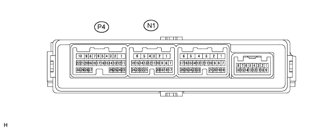
CHECK FRONT DOOR ECU RH
-
Disconnect the N1 and P4 ECU connectors.
-
Measure the voltage and resistance according to the value(s) in the table below.
Terminal No. (Symbols) Wiring Color Terminal Description Condition Specified Condition N1-1 (GND) - Body ground W-B - Body ground Ground Always Below 1 Ω *P4-28 (PSE) - N1-1 (GND) O - W-B Ground Always Below 1 Ω P4-28 (DSE) - N1-1 (GND) O - W-B Ground Always Below 1 Ω P4-29 (MSWE) - N1-1 (GND) V - W-B Ground Always Below 1 Ω P4-11 (CPUB) - N1-1 (GND) R - W-B Battery (ECU power source) Always 11 to 14 V P4-6 (BDR) - N1-1 (GND) O - W-B Battery (ECU power source) Always 11 to 14 V P4-3 (SIG) - N1-1 (GND) V - W-B Engine switch signal Engine switch on (IG) 11 to 14 V P4-16 (MM) - P4-29 (MSWE) O - V Memory switch signal Memory switch set off 10 kΩ or higher Memory switch set on Below 1 Ω P4-13 (M1) - P4-29 (MSWE) R - W-B Memory switch signal Memory switch M1 off 10 kΩ or higher Memory switch M1 on Below 1 Ω P4-14 (M2) - P4-29 (MSWE) B - V Memory switch signal Memory switch M2 off 10 kΩ or higher Memory switch M2 on Below 1 Ω P4-15 (M3) - P4-29 (MSWE) Y - V Memory switch signal Memory switch M3 off 10 kΩ or higher Memory switch M3 on Below 1 Ω *P4-17 (PSDN) - N1-1 (GND) R - W-B Seat belt anchorage switch signal Anchorage switch down off 10 kΩ or higher Anchorage switch down on Below 1 Ω P4-17 (DSDN) - N1-1 (GND) R - W-B Seat belt anchorage switch signal Anchorage switch down off 10 kΩ or higher Anchorage switch down on Below 1 Ω *P4-18 (PSUP) - N1-1 (GND) B - W-B Seat belt anchorage switch signal Anchorage switch UP off 10 kΩ or higher Anchorage switch UP on Below 1 Ω P4-18 (DSUP) - N1-1 (GND) B - W-B Seat belt anchorage switch signal Anchorage switch UP off 10 kΩ or higher Anchorage switch UP on Below 1 Ω Tech Tips
*: for LHD
If the result is not as specified, there may be a malfunction on the wire harness side.
-
Reconnect the N1 and P4 ECU connectors.
-
Measure the voltage according to the value(s) in the table below.
Terminal No. (Symbols) Wiring Color Terminal Description Condition Specified Condition P4-16 (MM) - P4-29 (MSWE) O - V Memory switch signal Memory switch set off 11 to 14 V Memory switch set on Below 1 V P4-13 (M1) - P4-29 (MSWE) R - V Memory switch signal Memory switch M1 off 11 to 14 V Memory switch M1 on Below 1 V P4-14 (M2) - P4-29 (MSWE) B - V Memory switch signal Memory switch M2 off 11 to 14 V Memory switch M2 on Below 1 V P4-15 (M3) - P4-29 (MSWE) Y - V Memory switch signal Memory switch M3 off 11 to 14 V Memory switch M3 on Below 1 V *P4-17 (PSDN) - N1-1 (GND) R - W-B Seat belt anchorage switch signal Anchorage switch down off 11 to 14 V Anchorage switch down on Below 1 V P4-17 (DSDN) - N1-1 (GND) R - W-B Seat belt anchorage switch signal Anchorage switch down off 11 to 14 V Anchorage switch down on Below 1 V *P4-18 (PSUP) - N1-1 (GND) B - W-B Seat belt anchorage switch signal Anchorage switch UP off 11 to 14 V Anchorage switch UP on Below 1 V P4-18 (DSUP) - N1-1 (GND) B - W-B Seat belt anchorage switch signal Anchorage switch UP off 11 to 14 V Anchorage switch UP on Below 1 V Tech Tips
*: for LHD
If the result is not as specified, the ECU or switch may have a malfunction.
-