POWER SHOULDER BELT ANCHORAGE SYSTEM Seat Belt Anchor Position is not Memorized or does not Move to Memorized Position
DESCRIPTION
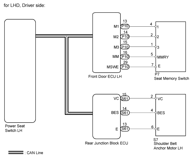
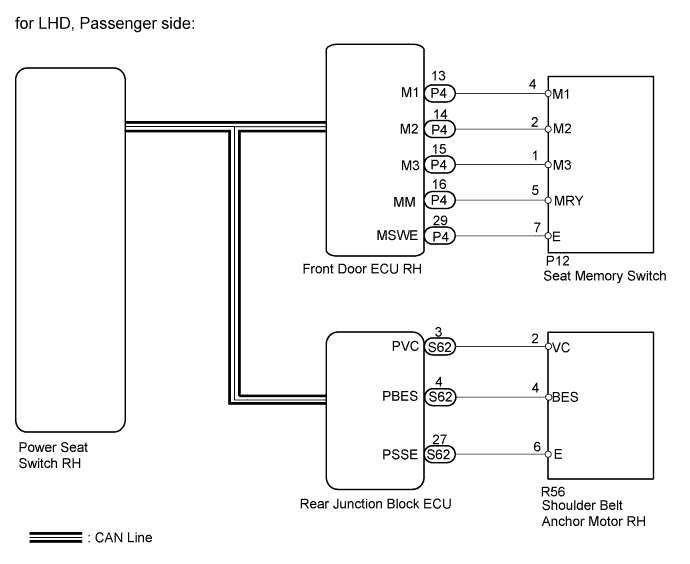
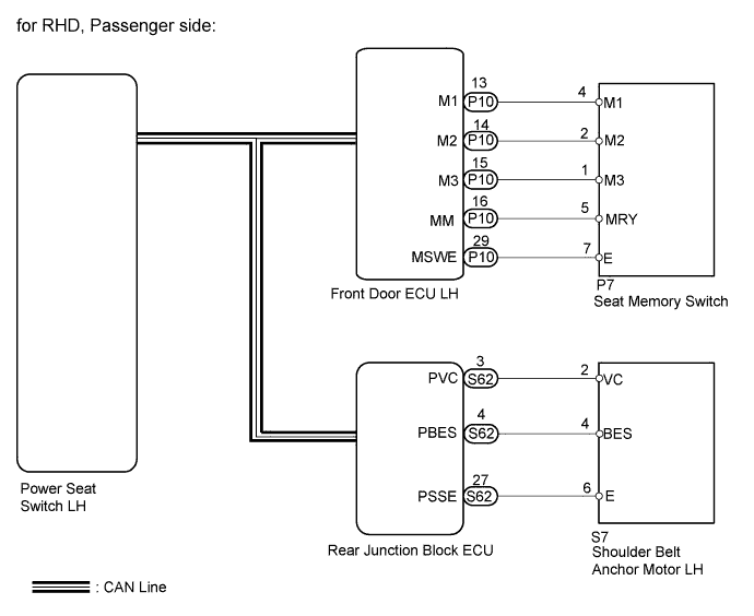
The shoulder belt anchor has a built-in position detection sensor. When the front door ECU LH or front door ECU RH receives a seat memory switch signal, it sends a memory store signal or call signal to the power seat switch LH or power seat switch RH and luggage room junction block assembly (rear junction block ECU). When the luggage room junction block assembly (rear junction block ECU) receives the memory store signal, it uses the position detection sensor to memorize the current position of the shoulder belt anchor. When the luggage room junction block assembly (rear junction block ECU) receives the call signal, it uses memorized shoulder belt anchor position and the position detection sensor to perform the call operation.
WIRING DIAGRAM

INSPECTION PROCEDURE
PROCEDURE
-
CHECK OPERATION OF SEAT MEMORY FUNCTION
-
Check which seat memory function is not operating correctly.
OK Result Proceed to Driver side A Passenger side B
B 
CHECK POWER BELT ANCHOR CONTROL FUNCTION Click here
A 
-
-
CHECK POWER BELT ANCHOR CONTROL FUNCTION
-
Operate the height adjustable anchor switch and check that the shoulder belt anchor operates normally.
Result Result Proceed to Operates normally A Shoulder belt anchor malfunctioning B
B 
GO TO DRIVER SIDE SEAT BELT ANCHOR DOES NOT OPERATE MANUALLY Click here
A
-
-
CHECK SEAT MEMORY SWITCH FUNCTION (SHOULDER BELT ANCHOR MEMORY FUNCTION)
-
Check that the seat belt anchor positions can be memorized using the seat memory switch.
OK Shoulder belt anchor positions can be memorized using seat memory switch.
NG
GO TO POWER SEAT CONTROL SYSTEM Click here
OK
-
-
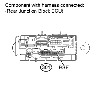
CHECK REAR JUNCTION BLOCK ECU
-
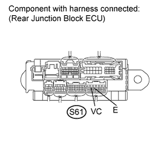
Measure the voltage according to the value(s) in the table below.
Standard Voltage Tester Connection Condition Specified Condition S61-13 (E) - S61-15 (VC) Always 11 to 14 V
NG
REPLACE LUGGAGE ROOM JUNCTION BLOCK ASSEMBLY (REAR JUNCTION BLOCK ECU)
OK
-
-
CHECK REAR JUNCTION BLOCK ECU (BES)
-
Measure the voltage according to the value(s) in the table below.
Standard Voltage Tester Connection Condition Specified Condition S61-14 (BES) - Body ground Seat belt anchor motor drives Alternating between 8 V and below 1 V S61-14 (BES) - Body ground Seat belt anchor motor stop Below 1 V
NG
CHECK HARNESS AND CONNECTOR (REAR JUNCTION BLOCK ECU - SHOULDER BELT ANCHOR MOTOR) Click here
OK 
REPLACE LUGGAGE ROOM JUNCTION BLOCK ASSEMBLY (REAR JUNCTION BLOCK ECU)
-
-
CHECK HARNESS AND CONNECTOR (REAR JUNCTION BLOCK ECU - SHOULDER BELT ANCHOR MOTOR)
-
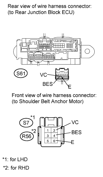
Disconnect the S61 ECU connector.
-
Disconnect the S7 or R56 anchor connector.
-
Measure the resistance according to the value(s) in the table below.
Standard Resistance for LHD: Tester Connection Condition Specified Condition S61-13 (E) - S7-6 (E) Always Below 1 Ω S61-14 (BES) - S7-4 (BES) S61-15 (VC) - S7-2 (VC) S61-13 (E) - Body ground Always 10 kΩ or higher S61-14 (BES) - Body ground S61-15 (VC) - Body ground for RHD: Tester Connection Condition Specified Condition S61-13 (E) - R56-6 (E) Always Below 1 Ω S61-14 (BES) - R56-4 (BES) S61-15 (VC) - R56-2 (VC) S61-13 (E) - Body ground Always 10 kΩ or higher S61-14 (BES) - Body ground S61-15 (VC) - Body ground
NG
REPAIR OR REPLACE HARNESS OR CONNECTOR
OK
REPLACE SHOULDER BELT ANCHOR MOTOR LH Click here
-
-
CHECK POWER BELT ANCHOR CONTROL FUNCTION
-
Operate the height adjustable anchor switch and check that the shoulder belt anchor operates normally.
Result Result Proceed to Operates normally A Shoulder belt anchor malfunctioning B
B
GO TO PASSENGER SIDE SEAT BELT ANCHOR DOES NOT OPERATE MANUALLY Click here
A
-
-
CHECK SEAT MEMORY SWITCH FUNCTION (SHOULDER BELT ANCHOR MEMORY FUNCTION)
-
Check that the seat belt anchor positions can be memorized using the seat memory switch.
OK Shoulder belt anchor positions can be memorized using seat memory switch.
NG
GO TO POWER SEAT CONTROL SYSTEM Click here
OK
-
-
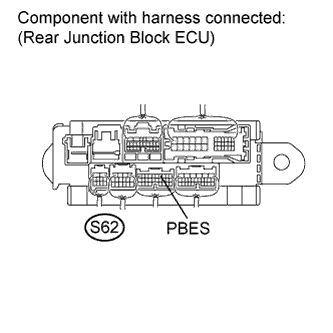
CHECK REAR JUNCTION BLOCK ECU
-

Measure the voltage according to the value(s) in the table below.
Standard Voltage Tester Connection Condition Specified Condition S62-27 (PSSE) - S62-3 (PVC) Always 11 to 14 V
NG
REPLACE LUGGAGE ROOM JUNCTION BLOCK ASSEMBLY (REAR JUNCTION BLOCK ECU)
OK
-
-
CHECK REAR JUNCTION BLOCK ECU (PBES SIGNAL)
-
Measure the voltage according to the value(s) in the table below.
Standard Voltage Tester Connection Condition Specified Condition S62-4 (PBES) - Body ground Seat belt anchor motor drives Alternating between 8 V and below 1 V S62-4 (PBES) - Body ground Seat belt anchor motor stop Below 1 V
NG
CHECK HARNESS AND CONNECTOR (REAR JUNCTION BLOCK ECU - SHOULDER BELT ANCHOR MOTOR) Click here
OK
REPLACE LUGGAGE ROOM JUNCTION BLOCK ASSEMBLY (REAR JUNCTION BLOCK ECU)
-
-
CHECK HARNESS AND CONNECTOR (REAR JUNCTION BLOCK ECU - SHOULDER BELT ANCHOR MOTOR)
-
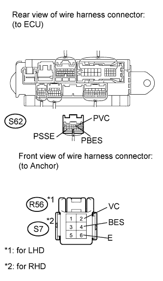
Disconnect the S62 ECU connector.
-
Disconnect the R56 or S7 anchor connector.
-
Measure the resistance according to the value(s) in the table below.
Standard Resistance for LHD: Tester Connection Condition Specified Condition S62-27 (PSSE) - R56-6 (E) Always Below 1 Ω S62-4 (PBES) - R56-4 (BES) S62-3 (PVC) - R56-2 (VC) S62-27 (PSSE) - Body ground Always 10 kΩ or higher S62-4 (PBES) - Body ground S62-3 (PVC) - Body ground for RHD: Tester Connection Condition Specified Condition S62-27 (E) - S7-6 (E) Always Below 1 Ω S62-4 (BES) - S7-4 (BES) S62-3 (VC) - S7-2 (VC) S62-27 (PSSE) - Body ground Always 10 kΩ or higher S62-4 (PBES) - Body ground S62-3 (PVC) - Body ground
NG
REPAIR OR REPLACE HARNESS OR CONNECTOR
OK
REPLACE SHOULDER BELT ANCHOR MOTOR RH Click here
-