SFI SYSTEM FREEZE FRAME DATA

-
DESCRIPTION
-
Freeze frame data records the engine conditions (fuel system, calculated load, engine coolant temperature, fuel trim, engine speed, vehicle speed, etc.) when a malfunction is detected. When troubleshooting, freeze frame data can help determine if the vehicle was moving or stationary, if the engine was warmed up or not, if the air-fuel ratio was Lean or Rich, and other data from the time the malfunction occurred.
Tech Tips
If it is impossible to replicate the problem even though a DTC is detected, confirm the freeze frame data.
-
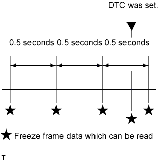
The ECM records engine conditions in the form of freeze frame data every 0.5 seconds. Using the GTS, five separate sets of freeze frame data, including the data values at the time when the DTC was set, can be checked.
-
3 data sets before the DTC was set.
-
1 data set when the DTC was set.
-
1 data set after the DTC was set.
-
These data sets can be used to simulate the condition of the vehicle around the time of the occurrence of the malfunction. The data may assist in identifying of the cause of the malfunction, and in judging whether it was temporary or not.
-
-
LIST OF FREEZE FRAME DATA
Tester Display Measurement Item Diagnostic Note Vehicle Speed Vehicle speed Speed indicated on speedometer Engine Speed Engine speed - Calculate load Calculated load Load calculated by ECM Vehicle Load Vehicle load - MAF Sensor 1 Supported Status of the MAF sensor 1 supported - MAF Sensor 1 Mass air flow rate for MAF meter (bank 1) If value approximately 0.0 g/s:
-
Mass air flow meter power source circuit open or shorted
-
VG circuit open or shorted
If value 160.0 g/s or more:
-
E2G circuit open
MAF Sensor 2 Supported Status of the MAF sensor 2 supported - MAF Sensor 2 Mass air flow rate for MAF meter (bank 2) If value approximately 0.0 g/s:
-
Mass air flow meter power source circuit open or shorted
-
VG circuit open or shorted
If value 160.0 g/s or more:
-
E2G circuit open
Atmosphere Pressure Atmosphere pressure - Coolant Temp Engine coolant temperature If value -40°C (-40°F), sensor circuit open
If value 140°C (284°F), sensor circuit shorted
Intake Air Temp B1S1 Supported Status of the intake air temp B1S1 supported - Intake Air Temp B1S1 Intake air temperature (bank 1 sensor 1) If value -40°C (-40°F), sensor circuit open
If value 140°C (284°F), sensor circuit shorted
Intake Air Temp B1S2 Supported Status of the intake air temp B1S2 supported - Intake Air Temp B1S2 Intake air temperature (bank 1 sensor 2) - Intake Air Temp B1S3 Supported Status of the intake air temp B1S3 supported - Intake Air Temp B1S3 Intake air temperature (bank 1 sensor 3) - Intake Air Temp B2S1 Supported Status of the intake air temp B2S1 supported - Intake Air Temp B2S1 Intake air temperature (bank 2 sensor 1) If value -40°C (-40°F), sensor circuit open
If value 140°C (284°F), sensor circuit shorted
Intake Air Temp B2S2 Supported Status of the intake air temp B2S2 supported - Intake Air Temp B2S2 Intake air temperature (bank 2 sensor 2) - Intake Air Temp B2S3 Supported Status of the intake air temp B2S3 supported - Intake Air Temp B2S3 Intake air temperature (bank 2 sensor 3) - Engine Run Time Accumulated engine running time - Initial Engine Coolant Temp Initial engine coolant temperature - Initial Intake Air Temp Initial intake air temperature - Battery Voltage Battery voltage - Accel Sens. No. 1 Volt % Absolute accelerator pedal position No. 1 - Accel Sens. No. 2 Volt % Absolute accelerator pedal position No. 2 - Throttle Sensor Volt % Throttle position Read value with engine switch on (IG) (Do not start engine) Throttl Sensor #2 Volt % Throttle position sensor #2 - Throttle Sensor Position Throttle position sensor Read value with engine switch on (IG) (Do not start engine) Throttle Motor DUTY Throttle actuator - Injector (Port) Fuel injector assembly - Injection Volum (Cylinder 1) Injection volume - Fuel Pump Speed Control Fuel pump speed control status - Fuel Pump/Speed Status Fuel pump/speed status - Current Fuel Type Status of the current fuel type - EVAP (Purge) VSV VSV for EVAP - EVAP Purge Flow Purge flow - Purge Density Learn Value Purge density learned value - EVAP Purge VSV VSV for EVAP - Purge Cut VSV Duty Purge cut VSV duty - Target Air-Fuel Ratio Air-fuel ratio - O2S B1S1 Heated oxygen sensor output Performing Control the Injection Volume or Control the Injection Volume for A/F Sensor function of Active Test enables technician to check output voltage of sensor O2S B1S2 Heated oxygen sensor output Performing Control the Injection Volume or Control the Injection Volume for A/F Sensor function of Active Test enables technician to check output voltage of sensor O2S B2S1 Heated oxygen sensor output Performing Control the Injection Volume or Control the Injection Volume for A/F Sensor function of Active Test enables technician to check output voltage of sensor O2S B2S2 Heated oxygen sensor output Performing Control the Injection Volume or Control the Injection Volume for A/F Sensor function of Active Test enables technician to check output voltage of sensor O2LR Switch Time B1S1 Lean to Rich response time (bank 1 sensor 1) - O2LR Switch Time B2S1 Lean to Rich response time (bank 2 sensor 1) - O2RL Switch Time B1S1 Rich to Lean response time (bank 1 sensor 1) - O2RL Switch Time B2S1 Rich to Lean response time (bank 2 sensor 1) - O2S Impedance B1S2 Heated oxygen sensor impedance - O2S Impedance B2S2 Heated oxygen sensor impedance - O2 Heater B1S1 Heated oxygen sensor heater - O2 Heater B1S2 Heated oxygen sensor heater - O2 Heater B2S1 Heated oxygen sensor heater - O2 Heater B2S2 Heated oxygen sensor heater - O2 Heater Curr Val B1S1 Heated oxygen sensor current - O2 Heater Curr Val B1S2 Heated oxygen sensor current - O2 Heater Curr Val B2S1 Heated oxygen sensor current - O2 Heater Curr Val B2S2 Heated oxygen sensor current - Short FT #1 Short-term fuel trim Short-term fuel compensation used to maintain air fuel ratio at stoichiometric air fuel ratio Long FT #1 Long-term fuel trim
-
Overall fuel compensation carried out in long term to compensate for continual deviation of short-term fuel trim from central value
-
Air fuel ratio feedback leaning is divided up according to the engine operating range (engine speed x load), and separate values are stored for each operating range. "Long FT #1" indicates the learned value for the current operating range. [A/F Learn Value Idle #1], [A/F Learn Value Low #1], [A/F Learn Value Mid1 #1], [A/ F Learn Value Mid2 #1] and [A/ F Learn Value High #1] indicate the leaned values for the different operating ranges. The learned value that is the same as "Long FT #1" indicates the current engine operating range.
A/F Learn Value Idle #1 - Learning is performed when idling with the engine warmed up (engine coolant temperature is 80°C [176°F] or higher). A/F Learn Value Low #1 - Learning is performed when driving with the engine warmed up (engine coolant temperature is 80°C [176°F] or higher) and operating in the low load range (when the range of engine loads is divided into four parts). A/F Learn Value Mid1 #1 - Learning is performed when driving with the engine warmed up (engine coolant temperature is 80°C [176°F] or higher) and operating in the midsize load range closer to the low load range (when the range of engine loads is divided into four parts). A/F Learn Value Mid2 #1 - Learning is performed when driving with the engine warmed up (engine coolant temperature is 80°C [176°F] or higher) and operating in the midsize load range closer to the high load range (when the range of engine loads is divided into four parts). A/F Learn Value High #1 - Learning is performed when driving with the engine warmed up (engine coolant temperature is 80°C [176°F] or higher) and operating in the high load range (when the range of engine loads is divided into four parts). Total FT #1 Total fuel trim - Short FT #2 Short-term fuel trim Short-term fuel compensation used to maintain air fuel ratio at stoichiometric air fuel ratio Long FT #2 Long-term fuel trim
-
Overall fuel compensation carried out in long term to compensate for continual deviation of short-term fuel trim from central value
-
Air fuel ratio feedback leaning is divided up according to the engine operating range (engine speed x load), and separate values are stored for each operating range. "Long FT #2" indicates the learned value for the current operating range. [A/F Learn Value Idle #2], [A/F Learn Value Low #2], [A/F Learn Value Mid1 #2], [A/ F Learn Value Mid2 #2] and [A/ F Learn Value High #2] indicate the leaned values for the different operating ranges. The learned value that is the same as "Long FT #2" indicates the current engine operating range.
A/F Learn Value Idle #2 - Learning is performed when idling with the engine warmed up (engine coolant temperature is 80°C [176°F] or higher). A/F Learn Value Low #2 - Learning is performed when driving with the engine warmed up (engine coolant temperature is 80°C [176°F] or higher) and operating in the low load range (when the range of engine loads is divided into four parts). A/F Learn Value Mid1 #2 - Learning is performed when driving with the engine warmed up (engine coolant temperature is 80°C [176°F] or higher) and operating in the midsize load range closer to the low load range (when the range of engine loads is divided into four parts). A/F Learn Value Mid2 #2 - Learning is performed when driving with the engine warmed up (engine coolant temperature is 80°C [176°F] or higher) and operating in the midsize load range closer to the high load range (when the range of engine loads is divided into four parts). A/F Learn Value High #2 - Learning is performed when driving with the engine warmed up (engine coolant temperature is 80°C [176°F] or higher) and operating in the high load range (when the range of engine loads is divided into four parts). Total FT #2 Total fuel trim - Fuel System Status #1 Fuel system status (Bank 1)
-
OL (Open Loop): Has not yet satisfied conditions to go to closed loop
-
CL (Closed Loop): Using heated oxygen sensor (sensor 1) as feedback for fuel control
-
OL DRIVE: Open loop due to driving conditions (fuel enrichment)
-
OL FAULT: Open loop due to detected system fault
-
CL FAULT: Closed loop but heated oxygen sensor (sensor 1), which used for fuel control, malfunctioning
Fuel System Status #2 Fuel system status (Bank 2)
-
OL (Open Loop): Has not yet satisfied conditions to go to closed loop
-
CL (Closed Loop): Using heated oxygen sensor (sensor 1) as feedback for fuel control
-
OL DRIVE: Open loop due to driving conditions (fuel enrichment)
-
OL FAULT: Open loop due to detected system fault
-
CL FAULT: Closed loop but heated oxygen sensor (sensor 1), which used for fuel control, malfunctioning
O2FT B1S1 Fuel trim at heated oxygen sensor Same as Short FT #1 O2FT B2S1 Fuel trim at heated oxygen sensor Same as Short FT #1 IGN Advance Ignition advance - Knock Feedback Value Knocking feedback value - Knock Correct Learn Value Knocking correction learned value - ACIS Motor Duty ACIS motor duty - Actual VVT Angle #1 Actual VVT displacement angle (bank 1) This item is used for freeze frame data only Actual VVT Angle #2 Actual VVT displacement angle (bank 2) This item is used for freeze frame data only Actual VVT Ex Angle #1 Actual VVT exhaust displacement angle (bank 1) This item is used for freeze frame data only Actual VVT Ex Angle #2 Actual VVT exhaust displacement angle (bank 2) This item is used for freeze frame data only Catalyst Temp B1S1 Catalyst temperature - Catalyst Temp B2S1 Catalyst temperature - Catalyst Temp B1S2 Catalyst temperature - Catalyst Temp B2S2 Catalyst temperature - Starter Signal Starter signal - Starter Control Starter control - Starter Relay Starter relay - ACC Relay ACC relay - Neutral Position SW Signal Park/neutral position switch assembly signal - Stop Light Switch Stop light switch assembly - A/C Signal A/C signal - Idle Up Signal Idle up signal - Closed Throttle Position SW Closed throttle position switch - Fuel Cut Condition Fuel cut condition - Immobiliser Communication Immobiliser communication - TC Terminal TC terminal status - Time after DTC Cleared Cumulative time after DTC cleared - Distance from DTC Cleared Accumulated distance driven after DTCs cleared - Warmup Cycle Cleared DTC Warmup cycles after DTCs cleared - Dist Batt Cable Disconnect Total distance vehicle driven after battery cable disconnected - TC and TE1 TC and TE1 terminals of DLC3 - Ignition Trig. Count Ignition - Cylinder #1 Misfire Count Cylinder #1 misfire count - Cylinder #2 Misfire Count Cylinder #2 misfire count - Cylinder #3 Misfire Count Cylinder #3 misfire count - Cylinder #4 Misfire Count Cylinder #4 misfire count - Cylinder #5 Misfire Count Cylinder #5 misfire count - Cylinder #6 Misfire Count Cylinder #6 misfire count - Cylinder #7 Misfire Count Cylinder #7 misfire count - Cylinder #8 Misfire Count Cylinder #8 misfire count - All Cylinders Misfire Count Misfire count of all cylinders - Multi Cylinders Misfire Count Misfire count of multiple cylinders - Misfire RPM Misfire RPM - Misfire Load Misfire load - Misfire Margin Misfire monitoring - Electric Fan Motor Fan motor status - Brake Override System Brake override system status - Idle Fuel Cut Idle fuel cut ON when throttle valve fully closed and engine speed over 2800 rpm FC TAU FC TAU Fuel cut being performed under very light load to prevent incomplete engine combustion Communication with ECT Status of communication with ECT - Electrical Load Signal 1 Electrical load signal - Received MIL from ECT MIL status from ECT - Shift Position Sig from ECT Shift position from ECT - A/T Oil Temp from ECT A/T oil temperature from ECT - SPD (NO) Output shaft speed - SPD (NT) Input shaft speed - ECT Lock Up ECT lock up status - SPD (SP2) Output shaft speed - Shift SW Status (P Range) Park/neutral position switch assembly status - Pattern Switch (PWR/M) SPORT mode status - Shift SW Status (R Range) Park/neutral position switch assembly status - Shift SW Status (N Range) Park/neutral position switch assembly status - Shift SW Status (N, P Range) Supported Status of park/neutral position switch (N or P) supported - Shift SW Status (N, P Range) Park/neutral position switch assembly status - Sports Shift Up SW Sport shift up switch status - Sports Shift Down SW Sport shift down switch status - Sports Mode Selection SW Sport mode select switch status - Shift SW Status (D Range) Park/neutral position switch assembly status - Normal Mode Switch Combination switch (NORMAL) status - Sports Mode Switch Combination switch (SPORT) status - ECO Switch ECO mode status - Snow or 2nd Start Mode Combination switch (SNOW) status - -