SFI SYSTEM, Diagnostic DTC:P0031, P0032, P0051, P0052

| DTC Code | DTC Name |
|---|---|
| P0031 | Oxygen Sensor Heater Control Circuit Low (Bank 1 Sensor 1) |
| P0032 | Oxygen Sensor Heater Control Circuit High (Bank 1 Sensor 1) |
| P0051 | Oxygen Sensor Heater Control Circuit Low (Bank 2 Sensor 1) |
| P0052 | Oxygen Sensor Heater Control Circuit High (Bank 2 Sensor 1) |
DESCRIPTION
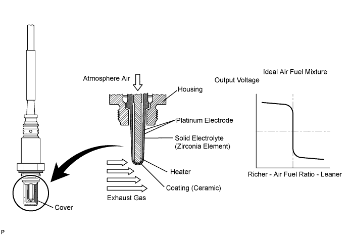
The heated oxygen sensor is used to monitor oxygen concentration in the exhaust gas. For optimum catalytic converter operation, the air-fuel mixture must be maintained near the ideal stoichiometric air-fuel ratio. The heated oxygen sensor output voltage changes suddenly in the vicinity of the stoichiometric air-fuel ratio. The ECM adjusts the fuel injection time so that the air-fuel ratio is nearly stoichiometric. The heated oxygen sensor generates a voltage between 0.1 and 0.9 V in response to oxygen concentration in the exhaust gas.
If the oxygen concentration in the exhaust gas increases, the air-fuel ratio is called LEAN. The heated oxygen sensor voltage drops below 0.45 V and the heated oxygen sensor informs the ECM of the LEAN condition.
If oxygen is not in the exhaust gas, the air-fuel ratio is called RICH. The heated oxygen sensor voltage increases above 0.45 V and the heated oxygen sensor informs the ECM of the RICH condition.
Tech Tips
-
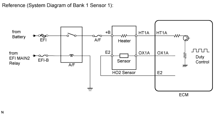
The ECM has a pulse width modulated control circuit to adjust current through the heater. The heated oxygen sensor heater circuit uses a relay on the +B side of the circuit.
-
When any of these DTCs are set, the ECM enters fail-safe mode. The ECM turns off the Heated Oxygen (HO2) Sensor heater in fail-safe mode. Fail-safe mode continues until the engine switch is turned off.
| DTC No. | DTC Detection Condition | Trouble Area |
|---|---|---|
| P0031 P0051 |
Heated oxygen sensor heater current is below 0.3 A when heater operates with +B greater than 11.5 V (1 trip detection logic) |
|
| P0032 P0052 |
Heater current exceeds 2 A when heater operates (1 trip detection logic) |
|
MONITOR DESCRIPTION
The sensing portion of the heated oxygen sensor has a zirconia element which is used to detect the oxygen concentration in the exhaust. If the zirconia element is at the proper temperature and the difference of the oxygen concentration between the inside and outside surface of the sensor is large, the zirconia element will generate voltage signals. In order to increase the oxygen concentration detecting capacity in the zirconia element, the ECM supplements the heat from the exhaust with heat from a heating element inside the sensor. When the current in the heated oxygen sensor heater is out of the standard operating range, the ECM interprets this as a fault in the heated oxygen sensor heater. The ECM illuminates the MIL and sets a DTC.
Normally, the heated oxygen sensor heater current is 0.4 to 1.0 A.
Example:
The ECM will set a high current DTC if the current in the sensor is more than 2 A. Similarly, the ECM will set a low current DTC if the current is less than 0.3 A.
The monitor runs if the engine is started and run at idle for 9 minutes or more.
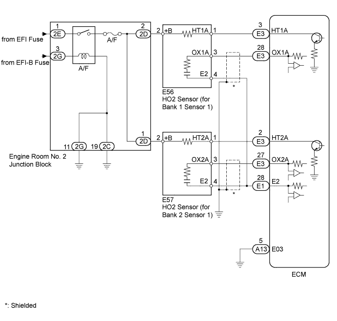
WIRING DIAGRAM
INSPECTION PROCEDURE
Tech Tips
-
Read freeze frame data using the intelligent tester. Freeze frame data records the engine conditions when a malfunction is detected. When troubleshooting, freeze frame data can help determine if the vehicle was running or stopped, if the engine was warmed up or not, if the air-fuel ratio was LEAN or RICH, and other data from the time the malfunction occurred.
-
Bank 1 refers to the bank that includes No. 1 cylinder.
-
Bank 2 refers to the bank that does not include No. 1 cylinder.
-
No. 1 cylinder is located in the front part of the engine, opposite the transmission.
-
Sensor 1 refers to the sensor closest to the engine body.
-
Sensor 2 refers to the sensor farthest away from the engine body.
PROCEDURE
-
INSPECT HEATED OXYGEN SENSOR (HEATER RESISTANCE)
-
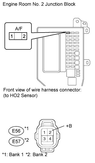
Disconnect the E56 and E57 sensor connectors.
-
Measure the resistance according to the value(s) in the table below.
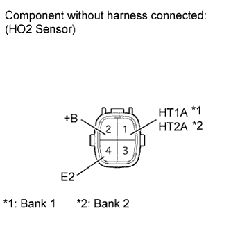
Standard resistance Tester Connection Condition Specified Condition 1 (HT1A) - 2 (+B) Always 11 to 16 Ω 1 (HT2A) - 2 (+B) Always 11 to 16 Ω 1 (HT1A) - 4 (E2) Always 10 kΩ or higher 1 (HT2A) - 4 (E2) Always 10 kΩ or higher
NG 
REPLACE HEATED OXYGEN SENSOR Click here
OK 
-
-
CHECK HARNESS AND CONNECTOR (HEATER POWER SOURCE)
-
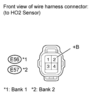
Disconnect the E56 or E57 sensor connector.
-
Turn the engine switch on (IG).
-
Measure the voltage according to the value(s) in the table below.
Standard voltage Terminal Connections Switch Condition Specified Condition E56-2 (+B) - Body ground Engine switch on (IG) 11 to 14 V E57-2 (+B) - Body ground Engine switch on (IG) 11 to 14 V
NG 
INSPECT A/F FUSE Click here
OK
-
-
CHECK HARNESS AND CONNECTOR (ECM - HEATED OXYGEN SENSOR AND BODY GROUND)
-
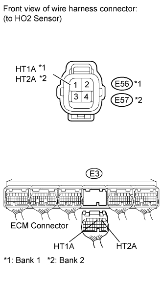
Disconnect the E56 and E57 sensor connectors.
-
Disconnect the E3 ECM connector.
-
Measure the resistance according to the value(s) in the table below.
Standard resistance Tester Connection Condition Specified Condition E56-1 (HT1A) - E3-3 (HT1A) Always Below 1 Ω E57-1 (HT2A) - E3-2 (HT2A) Always Below 1 Ω E56-1 (HT1A) or E3-3 (HT1A) - Body ground Always 10 kΩ or higher E57-1 (HT2A) or E3-2 (HT2A) - Body ground Always 10 kΩ or higher -
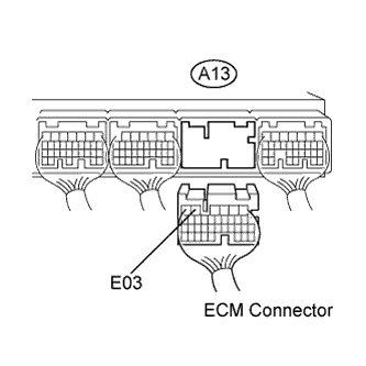
Disconnect the A13 ECM connector.
-
Measure the resistance according to the value(s) in the table below.
Standard resistance Tester Connection Condition Specified Condition A13-5 (E03) - Body ground Always Below 1 Ω
NG
REPAIR OR REPLACE HARNESS OR CONNECTOR
OK 
REPLACE ECM Click here
-
-
INSPECT A/F FUSE
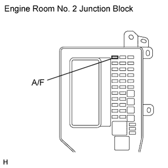
-
Remove the A/F fuse from the engine room No. 2 junction block.
-
Measure the resistance according to the value(s) in the table below.
Standard resistance Tester Connection Condition Specified Condition A/F fuse Always Below 1 Ω
NG
CHECK FOR SHORT IN ALL HARNESSES AND CONNECTORS CONNECTED TO FUSE AND REPLACE FUSE
OK
-
-
INSPECT ENGINE ROOM NO. 2 JUNCTION BLOCK (A/F RELAY)
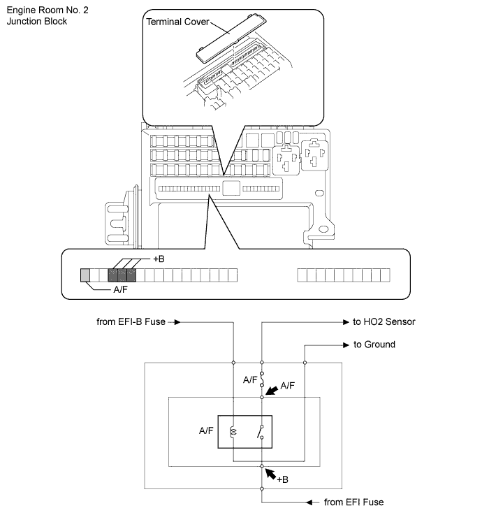
-
Remove the terminal cover.
-
Measure the voltage according to the value(s) in the table below.
Standard voltage Tester Connection Switch Condition Specified Condition +B - Body ground Always 11 to 14 V A/F - Body ground Engine switch on (IG) 11 to 14 V
NG
REPLACE ENGINE ROOM NO. 2 JUNCTION BLOCK
OK
-
-
CHECK HARNESS AND CONNECTOR (HEATED OXYGEN SENSOR - A/F FUSE)
-
Disconnect the E56 and E57 sensor connectors.
-
Remove the A/F fuse from the engine room No. 2 junction block.
-
Measure the resistance according to the value(s) in the table below.
Standard resistance Tester Connection Condition Specified Condition A/F fuse terminal 2 - E56-2 (+B) Always Below 1 Ω A/F fuse terminal 2 - E57-2 (+B) Always Below 1 Ω A/F fuse terminal 2 or E56-2 (+B) - Body ground Always 10 kΩ or higher A/F fuse terminal 2 or E57-2 (+B) - Body ground Always 10 kΩ or higher
NG
REPAIR OR REPLACE HARNESS OR CONNECTOR
OK
REPLACE ENGINE ROOM NO. 2 JUNCTION BLOCK
-