БЕССТУПЕНЧАТАЯ ТРАНСМИССИЯ В СБОРЕ УСТАНОВКА
-
INSTALL TORQUE CONVERTER ASSEMBLY
-
Clean the torque converter assembly set bolt holes.
-
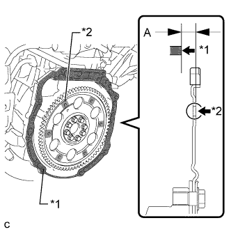
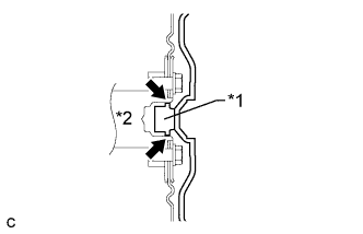
Using a vernier caliper and straightedge, measure dimension "A" between the continuously variable transaxle assembly contact surface of the engine assembly*1 and the torque converter assembly contact surface of the drive plate*2. (#)
Note
Make sure to deduct the thickness of the straightedge.
-
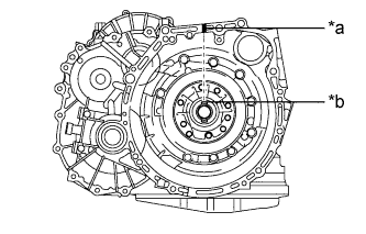
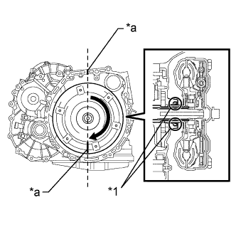
Text in Illustration *a Matchmark *b Groove Turn the front oil pump drive gear so that the groove is at the top and put a matchmark on the housing.
-
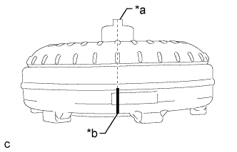
Text in Illustration *a Key *b Matchmark Put a matchmark on the torque converter assembly so that the position of its key is clearly indicated.
-
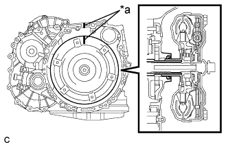
Text in Illustration *a Matchmark Align the matchmark on the housing with the one on the torque converter assembly and mesh the splines of the input shaft with the turbine runner splines.
Note
Install the torque converter assembly horizontally to the input shaft.
-
Text in Illustration *1 Oil Seal *a Matchmark Rotate the torque converter assembly and mesh the splines of the stator shaft with the stator splines.
Note
-
Do not damage the oil seal.
-
Install the torque converter assembly horizontally to the input shaft.
Tech Tips
Rotate the torque converter assembly approximately 180°.
-
-
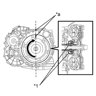
Text in Illustration *1 Oil Seal *a Matchmark Rotate the torque converter assembly again, align the matchmark on the housing with the one on the torque converter assembly and fit the key of the torque converter assembly into the groove of the oil pump drive gear.
Note
-
Do not push the torque converter assembly excessively when rotating it.
-
Do not damage the oil seal.
-
Install the torque converter assembly horizontally to the input shaft.
-
-
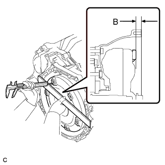
Using a vernier caliper and straightedge, measure dimension "B" shown in the illustration and check that dimension "B" is greater than dimension "A" (which was measured in step (#)).
Standard A + 1 mm (0.0394 in.) or more Note
Subtract the thickness of the straightedge from the measured value to gain dimension "B".
-
-
INSTALL ENGINE MOUNTING BRACKET LH
-
Install the engine mounting bracket LH to the continuously variable transaxle assembly with the 3 bolts.
- Torque:
- 64 N*m { 653 kgf*cm, 47 ft.*lbf }
-
-
INSTALL NO. 1 TRANSMISSION CONTROL CABLE BRACKET
-
Install the No. 1 transmission control cable bracket to the continuously variable transaxle assembly with the 2 bolts.
- Torque:
- 12 N*m { 122 kgf*cm, 9 ft.*lbf }
-
-
INSTALL CONTINUOUSLY VARIABLE TRANSAXLE ASSEMBLY
-
Text in Illustration *1 Torque Converter Assembly Centerpiece *2 Crankshaft Apply clutch spline grease to the circumference of the crankshaft contact surface with the torque converter assembly centerpiece.
Clutch Spline Grease Toyota Genuine Clutch Spline Grease or equivalent Maximum Spread About 1 g (0.0353 oz.) -
Confirm that the 2 knock pins are installed to the continuously variable transaxle assembly contact surface of the engine assembly before installing the continuously variable transaxle assembly.
-
Clean and degrease the bolt hole of the bolt (D).
-
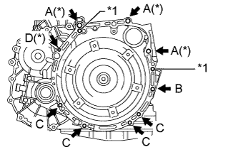
Text in Illustration *1 Knock Pin While keeping the engine assembly and continuously variable transaxle assembly level, align the knock pins with knock pin holes, and temporarily tighten the 8 bolts ((A), (B) and (C)) shown in the illustration.
Note
-
Make sure that the bolts and bolt holes (A)(*) and (D)(*) shown in the illustration are free of oil. Clean them if necessary.
-
Do not forcibly pry on the continuously variable transaxle assembly.
-
Make sure that the torque converter assembly rotates.
Tech Tips
-
for Bolt (A) : 55 mm (2.17 in.)
-
for Bolt (B) : 65 mm (2.56 in.)
-
for Bolt (C) : 32 mm (1.26 in.)
Bolt Length
-
-
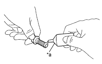
Text in Illustration *a Adhesive Apply adhesive to 2 or 3 threads on the end of a new bolt (D).
Note
-
Do not reuse bolt D.
-
After applying adhesive 1324, install the bolt (D) within 3 minutes to prevent foreign matter from attaching it.
Tech Tips
for Bolt (D) : 42 mm (1.65 in.)
-
-
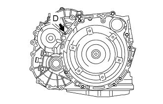
Temporarily tighten the bolt (D) shown in the illustration.
-
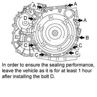
Tighten the 9 bolts ((A), (B), (C) and (D)) shown in the illustration.
- Torque:
- for Bolt (A)
- 64 N*m { 653 kgf*cm, 47 ft.*lbf }
- for Bolt (B)
- 46 N*m { 469 kgf*cm, 34 ft.*lbf }
- for Bolt (C)
- 44 N*m { 449 kgf*cm, 32 ft.*lbf }
- for Bolt (D)
- 20 N*m { 204 kgf*cm, 15 ft.*lbf }
Note
-
Make sure that the torque converter assembly rotates.
-
In order to ensure the sealing performance, leave the vehicle as it is for at least 1 hour after installing the bolt (D). (Do not start the engine.)
-
-
INSTALL OIL COOLER (w/o Air Cooled Transmission Oil Cooler)
-
Install the oil cooler to the continuously variable transaxle assembly with the 3 bolts.
- Torque:
- 12 N*m { 120 kgf*cm, 8 ft.*lbf }
-
Install the 2 oil cooler hoses and slide the 2 clips to secure them.
-
Install the water by-pass hose and 2 oil cooler hoses and slide the 3 clips to secure them.
-
-
INSTALL OIL COOLER (w/ Air Cooled Transmission Oil Cooler)
-
Install the oil cooler to the continuously variable transaxle assembly with the 3 bolts.
- Torque:
- 12 N*m { 120 kgf*cm, 8 ft.*lbf }
-
Install the 2 water by-pass hoses and slide the 2 clips to secure them.
-
Install the 2 oil cooler hoses and slide the 4 clips to secure them.
-
-
INSTALL WIRE HARNESS CLAMP BRACKET
-
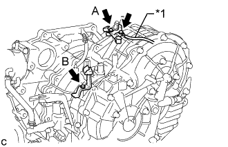
Text in Illustration *1 Ground Cable Install the shift cable bracket and 2 wire harness clamp brackets to the continuously variable transaxle assembly with the 2 bolts.
- Torque:
- for Bolt (A)
- 5.0 N*m { 51 kgf*cm, 44 in.*lbf }
- for Bolt (B)
- 8.4 N*m { 86 kgf*cm, 74 in.*lbf }
-
Install the ground cable to the wire harness clamp bracket with the bolt.
- Torque:
- 8.4 N*m { 86 kgf*cm, 74 in.*lbf }
-
-
INSTALL ENGINE WIRE
-
Install the 2 wire harness clamps and connect the oil pressure sensor connector to the continuously variable transaxle assembly.
-
Install the 4 wire harness clamps and connect the 3 revolution sensor connectors, park/neutral position switch assembly connector and transmission wire connector to the continuously variable transaxle assembly.
-
-
INSTALL STARTER ASSEMBLY (for 1.6 kW Type)
-
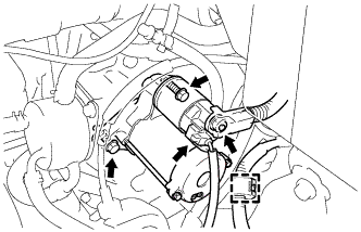
Установите стартер и закрепите его 2 болтами.
- Torque:
- 37 Н*м { 377 кгс*см, 27 фунт-сила-футов }
-
Подсоедините разъем стартера.
-
Подсоедините зажим.
-
Заверните гайку контакта и закройте ее колпачком.
- Torque:
- 9,8 Н*м { 100 кгс*см, 87 фунт-сила-дюймов }
-
-
INSTALL STARTER ASSEMBLY (for 1.7 kW Type)
-
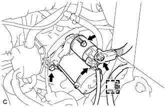
Install the starter with the 2 bolts.
- Torque:
- 37 N*m { 377 kgf*cm, 27 ft.*lbf }
-
Connect the starter connector.
-
Connect the clamp.
-
Install the terminal nut, and cover the nut with the cap.
- Torque:
- 9.8 N*m { 100 kgf*cm, 87 in.*lbf }
-
-
INSTALL REAR ENGINE MOUNTING BRACKET
-
Install the rear engine mounting bracket to the continuously variable transaxle assembly with the 3 bolts.
- Torque:
- 45 N*m { 459 kgf*cm, 33 ft.*lbf }
-
-
INSTALL FRONT ENGINE MOUNTING BRACKET
-
Install the front engine mounting bracket to the continuously variable transaxle assembly with the 3 bolts.
- Torque:
- 64 N*m { 653 kgf*cm, 47 ft.*lbf }
-
-
TEMPORARILY TIGHTEN REAR ENGINE MOUNTING INSULATOR
-
Временно установите подушку задней опоры двигателя на кронштейн опоры двигателя и закрепите ее стяжным болтом.
-
-
TEMPORARILY TIGHTEN FRONT ENGINE MOUNTING INSULATOR
-
Установите подушку передней опоры двигателя и предварительно закрепите ее стяжным болтом и гайкой.
-
-
INSTALL FRONT CROSS MEMBER SUB-ASSEMBLY
-
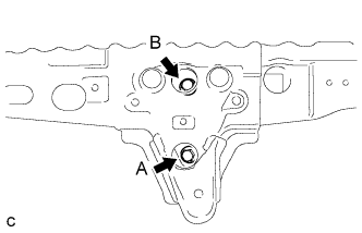
Временно закрепите переднюю поперечину на передней подушке опоры двигателя с помощью болта A, а затем затяните болт B.
- Torque:
- 95 Н*м { 969 кгс*см, 70 фунт-сила-футов }
-
Затяните болт А.
- Torque:
- 95 Н*м { 969 кгс*см, 70 фунт-сила-футов }
-
-
INSTALL ENGINE ASSEMBLY WITH TRANSAXLE
Tech Tips
See the steps from "Install Engine Assembly with Transaxle" through "Check ABS Speed Sensor Signal" Click here.
-
RESET MEMORY
-
Perform Reset Memory (CVT initialization) when replacing the continuously variable transaxle assembly Click here.
-