СИСТЕМА АВТОМАТИЧЕСКОЙ ТРАНСМИССИИ КОНТАКТЫ ECM
-
ECM
Tech Tips
Each ECM terminal's standard voltage is shown in the table below.
In the table, first follow the information under "Condition". Look under "Terminal No. (Symbols)" for the terminals to inspected. The standard voltage between the terminals is shown under "Specified Condition".
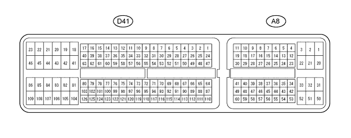
Use the illustration above as a reference for the ECM terminals.
Terminals No. (Symbols) Wiring Color Terminal Description Condition Specified Condition D41-56 (D) - D41-104 (E1) W - BR D shift position switch signal Engine switch on (IG) and shift lever D and S position 11 to 14 V Engine switch on (IG) and shift lever except D and S position Below 1 V D41-53 (R) - D41-104 (E1) R - BR R shift position switch signal Engine switch on (IG) and shift lever R position 11 to 14 V Engine switch on (IG) and shift lever except R position Below 1 V A8-8 (SPD) - D41-104 (E1) BE - BR Speed signal Vehicle speed 20 km/h (12 mph) Pulse generation
(See waveform 7)
A8-36 (STP) - D41-104 (E1) R - BR Stop light switch signal Brake pedal is depressed 7.5 to 14 V Brake pedal is released Below 1.5 V A8-51 (SFTD) - D41-104 (E1) GR - BR Down shift switch signal Engine switch on (IG) and shift lever S position 11 to 14 V Engine switch on (IG) and shift lever "-" position (Down shift) Below 1 V A8-16 (SFTU) - D41-104 (E1) P - BR Up shift switch signal Engine switch on (IG) and shift lever S position 11 to 14 V Engine switch on (IG) and shift lever "+" position (Up shift) Below 1 V D41-74 (S) - D41-104 (E1) G - BR S shift position switch signal Engine switch on (IG) and shift lever S, "+" and "-" position 11 to 14 V Engine switch on (IG) and shift lever except S, "+" and "-" position Below 1 V D41-73 (P) - D41-104 (E1) V - BR P shift position switch signal Engine switch on (IG) and shift lever P position 11 to 14 V Engine switch on (IG) and shift lever except P position Below 1 V D41-54 (N) - D41-104 (E1) L - BR N shift position switch signal Engine switch on (IG) and shift lever N position 11 to 14 V Engine switch on (IG) and shift lever except N position Below 1 V D41-52 (STAR (NSW)) - D41-104 (E1) G - BR Park neutral switch signal Engine switch on (IG) and shift lever P and N position Below 2 V Engine switch on (IG) and shift lever except P and N position 11 to 14 V D41-79 (DSL) - D41-104 (E1) P - BR DSL solenoid signal Vehicle speed 65 km/h (40 mph), lock-up (ON to OFF) Pulse generation
(See waveform 2)
D41-78 (S4) - D41-104 (E1) LG - BR S4 solenoid signal Engine switch on (IG) Below 1 V 4th gear 11 to 14 V Except 4th gear Below 1 V D41-58 (SL2+) - D41-59 (SL2-) G - W SL2 solenoid signal Engine idle speed Pulse generation
(See waveform 3)
Engine switch on (IG) Below 1 V 1st or 2nd gear 11 to 14 V 3rd or O/D gear Below 1 V D41-57 (SL1+) - D41-77 (SL1-) L - R SL1 solenoid signal Engine idle speed Pulse generation
(See waveform 4)
Engine switch on (IG) 11 to 14 V 1st gear 11 to 14 V Except 1st gear Below 1 V D41-101 (NC+) - D41-102 (NC-) R - G Speed sensor (NC) signal Vehicle speed 30 km/h (19 mph): (3rd gear)
Engine speed 1400 rpm
Pulse generation
(See waveform 5)
D41-125 (NT+) - D41-124 (NT-) P - V Speed sensor (NT) signal Vehicle speed 20 km/h (12 mph) Pulse generation
(See waveform 6)
D41-76 (SLT+) - D41-75 (SLT-) BR - Y SLT solenoid signal Engine idle speed Pulse generation
(See waveform 1)
D41-72 (THO1) - D41-95 (ETHO) G - BR ATF temperature sensor signal ATF temperature: 115°C (239°F) or more Below 1.5 V
-
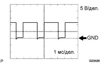
Waveform 1
Reference: Terminal SLT+ - SLT- Tool setting 5 V/DIV., 1ms./DIV. Vehicle condition Engine idle speed -
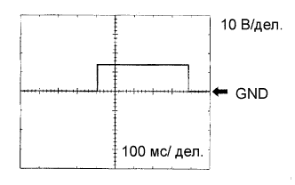
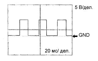
Waveform 2
Reference: Terminal DSL - E1 Tool setting 10 V/DIV., 100ms./DIV. Vehicle condition Vehicle speed 65 km/h (40 mph), lock-up (ON to OFF) -
Waveform 3
Reference: Terminal SL2+ - SL2- Tool setting 5 V/DIV., 1ms./DIV. Vehicle condition Engine idle speed -
Waveform 4
Reference: Terminal SL1+ - SL1- Tool setting 5 V/DIV., 1ms./DIV. Vehicle condition Engine idle speed -
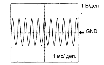
Waveform 5
Reference: Terminal NC+ - NC- Tool setting 1 V/DIV., 1ms./DIV. Vehicle condition Vehicle speed 30 km/h (19 mph): (3rd gear)
Engine speed 1400 rpm
-
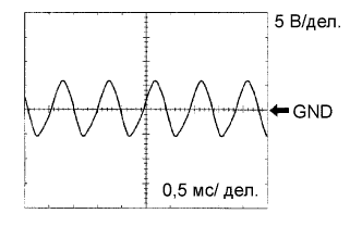
Waveform 6
Reference: Terminal NT+ - NT- Tool setting 5 V/DIV., 0.5ms./DIV. Vehicle condition Vehicle speed 20 km/h (12 mph) -
Waveform 7
Reference: Terminal SPD - E1 Tool setting 5 V/DIV., 20ms./DIV. Vehicle condition Vehicle speed 20 km/h (12 mph) Tech Tips
Depending on the vehicle, the output waveform voltage, influenced by optionally installed systems, may become 5V.
-