МАСЛЯНЫЙ НАСОС СНЯТИЕ

Tech Tips
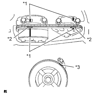
Check whether the engine is TMC made or not by referring to the following illustration.
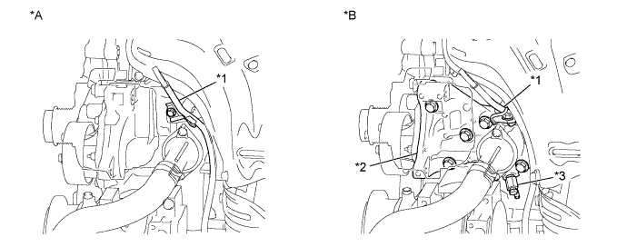
| *A | for TMC Made Engine | *B | except TMC Made Engine |
| *1 | Engine Oil Level Dipstick Guide | *2 | Water Inlet Housing |
| *3 | Water Inlet Housing Drain Cock Assembly | - | - |
-
REMOVE AUTOMATIC TRANSAXLE ASSEMBLY (for Automatic Transaxle)
-
REMOVE CONTINUOUSLY VARIABLE TRANSAXLE ASSEMBLY (for CVT)
-
REMOVE DRIVE PLATE AND RING GEAR SUB-ASSEMBLY
-
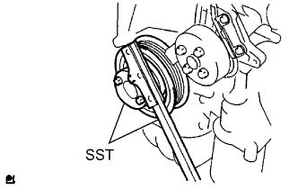
Using SST, hold the crankshaft.
- SST
- 09213-54015 ( 91651-60855 )
- 09330-00021
-
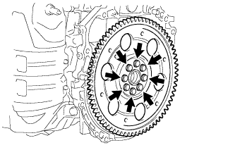
Remove the 8 bolts, rear spacer, drive plate and ring gear sub-assembly, and front spacer.
-
-
SET ENGINE STAND
-
REMOVE ENGINE HANGERS
-
Remove the engine hangers.
-
-
REMOVE IGNITION COIL ASSEMBLY
-
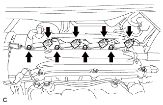
Disconnect the 4 ignition coil connectors.
-
Remove the 4 bolts and 4 ignition coils.
-
-
REMOVE CYLINDER HEAD COVER SUB-ASSEMBLY
-
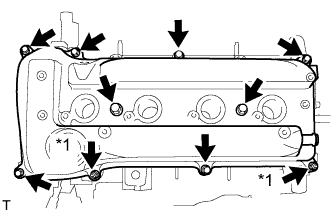
Text in Illustration *1 Nut Remove the 8 bolts and 2 nuts, and remove the cylinder head cover.
-
-
REMOVE IDLER PULLEY SUB-ASSEMBLY
-
Remove the 2 bolts and idler pulley bracket.
-
-
REMOVE OIL PAN SUB-ASSEMBLY
-
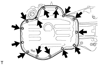
Remove the 12 bolts and 2 nuts.
-
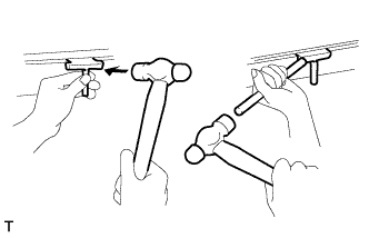
Insert the blade of an oil pan seal cutter between the crankcase, chain cover and oil pan, then cut through the applied sealer and remove the oil pan.
Note
Be careful not to damage the contact surfaces of the crankcase, chain cover or oil pan.
-
-
SET NO. 1 CYLINDER TO TDC/COMPRESSION
-
Text in Illustration *1 Timing Mark *2 Paint Mark *3 Groove Turn the crankshaft pulley until the groove and the timing mark "0" on the timing chain cover are aligned.
-
Check that each timing mark on the camshaft timing gear and sprocket is aligned with each timing mark located on the No. 1 and No. 2 bearing caps as shown in the illustration.
If not, turn the crankshaft pulley 1 revolution (360°) to align the timing marks as illustrated.
-
Place paint marks on the chain in alignment with the timing marks on the camshaft timing gear and camshaft timing sprocket.
-
-
REMOVE CRANKSHAFT PULLEY
-
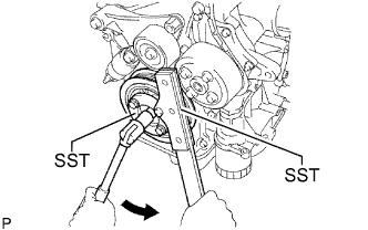
Using SST, hold the crankshaft pulley in place and loosen the pulley bolt.
- SST
- 09213-54015 ( 91651-60855 )
- 09330-00021
-
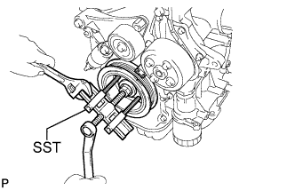
Using SST, remove the crankshaft pulley.
- SST
- 09950-50013 ( 09951-05010, 09952-05010, 09953-05020, 09954-05021 )
- 09950-40011 ( 09957-04010 )
Tech Tips
If necessary, remove the pulley and pulley bolt using SST.
-
-
REMOVE NO. 1 CHAIN TENSIONER ASSEMBLY
-
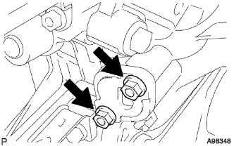
Remove the 2 nuts, No. 1 chain tensioner assembly and gasket.
Note
Do not turn the crankshaft without the No. 1 chain tensioner assembly.
-
-
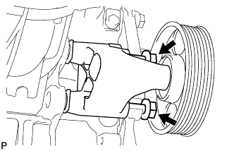
REMOVE V-RIBBED BELT TENSIONER ASSEMBLY
-
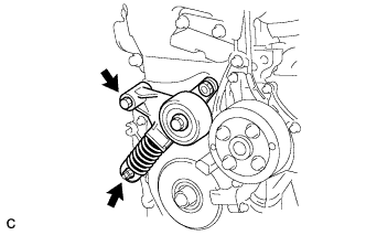
Remove the bolt, nut and belt tensioner.
-
-
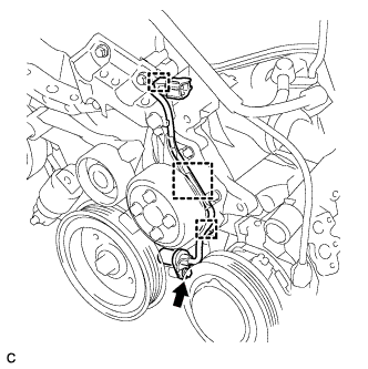
REMOVE CRANK POSITION SENSOR (for TMC Made Engine)
-
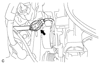
Disconnect the crank position sensor connector.
-
Disconnect the connector from the connector bracket.
-
Disconnect the 2 wire harness clamps.
-
Remove the bolt and crank position sensor.
-
-
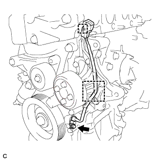
REMOVE CRANK POSITION SENSOR (except TMC Made Engine)
-
Disconnect the crank position sensor connector.
-
Disconnect the connector from the connector bracket.
-
Disconnect the wire harness clamp.
-
Remove the bolt and crank position sensor.
-
-
REMOVE TIMING CHAIN OR BELT COVER SUB-ASSEMBLY
-
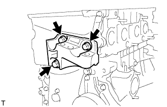
Remove the 3 bolts and engine mounting bracket RH.
-
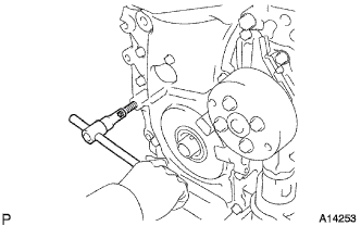
Using an E10 "TORX" socket, remove the stud bolt for the V-ribbed belt tensioner.
-
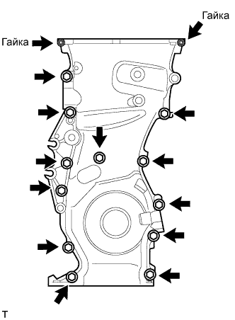
Remove the 12 bolts and 2 nuts.
-
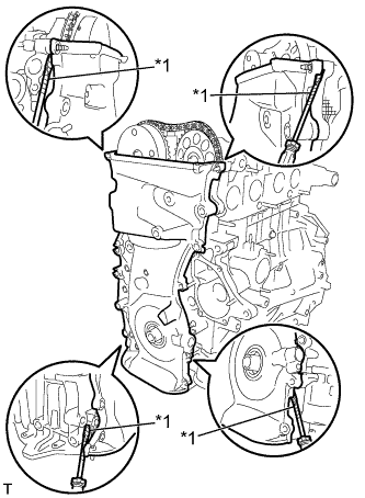
Text in Illustration *1 Protective Tape Remove the timing chain cover by prying the portions between the timing chain cover, cylinder head and cylinder block with a screwdriver.
Note
Be careful not to damage the contact surfaces of the timing chain cover, cylinder head or cylinder block.
Tech Tips
Tape the screwdriver tip before use.
-
-
REMOVE TIMING CHAIN COVER OIL SEAL
-
Text in Illustration *1 Protective Tape Place the timing chain cover on wooden blocks.
-
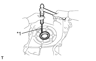
Using a screwdriver, pry out the oil seal.
Note
Do not damage the surface of the oil seal press fit hole.
Tech Tips
Tape the screwdriver tip before use.
-
-
REMOVE NO. 1 CRANKSHAFT POSITION SENSOR PLATE
-
Remove the No. 1 crankshaft position sensor plate.
-
-
REMOVE CHAIN TENSIONER SLIPPER
-
Remove the bolt and chain tensioner slipper.
-
-
REMOVE NO. 1 CHAIN VIBRATION DAMPER
-
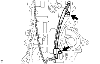
Remove the 2 bolts and No. 1 chain vibration damper.
-
-
REMOVE TIMING CHAIN GUIDE
-
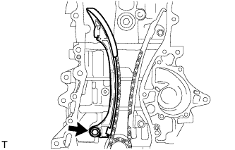
Remove the bolt and timing chain guide.
-
-
REMOVE CHAIN SUB-ASSEMBLY
-
REMOVE CRANKSHAFT TIMING GEAR OR SPROCKET
-
Remove the crankshaft timing gear or sprocket from the crankshaft.
-
-
REMOVE NO. 2 CHAIN SUB-ASSEMBLY
-
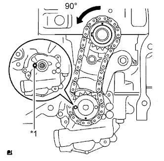
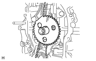
Text in Illustration *1 Groove Turn the crankshaft 90° counterclockwise to align the adjusting hole on the oil pump drive shaft sprocket with the groove on the oil pump.
-
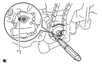
Text in Illustration *1 Groove Insert a 4 mm diameter bar into the adjusting hole of the oil pump drive shaft sprocket to lock the gear in position, and then remove the nut.
-
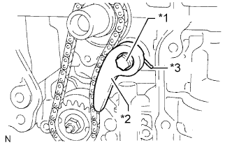
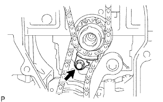
Text in Illustration *1 Bolt *2 Chain Tensioner Plate *3 Spring Remove the bolt, chain tensioner plate and spring.
-
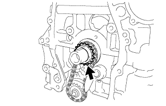
Remove the oil pump drive sprocket, oil pump drive shaft sprocket and No. 2 chain.
-
-
REMOVE OIL PUMP ASSEMBLY
-
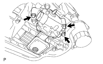
Remove the 3 bolts, oil pump and gasket.
-