МАСЛЯНЫЙ НАСОС УСТАНОВКА

Tech Tips
Check whether the engine is TMC made or not by referring to the following illustration.
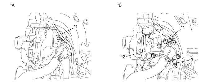
| *A | for TMC Made Engine | *B | except TMC Made Engine |
| *1 | Engine Oil Level Dipstick Guide | *2 | Water Inlet Housing |
| *3 | Water Inlet Housing Drain Cock Assembly | - | - |
-
INSTALL OIL PUMP ASSEMBLY
-
Install a new gasket and the oil pump with the 3 bolts.
- Torque:
- 19 N*m { 194 kgf*cm, 14 ft.*lbf }
-
-
INSTALL NO. 2 CHAIN SUB-ASSEMBLY
-
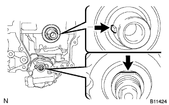
Set the crankshaft key into the left horizontal position.
-
Turn the oil pump drive shaft so that the cutout faces upward.
-
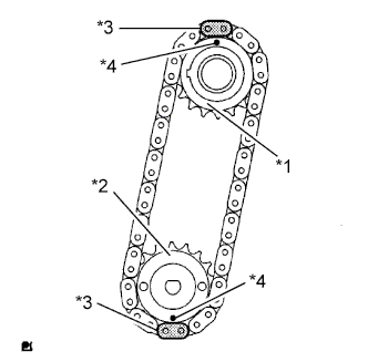
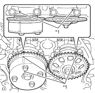
Text in Illustration *1 Oil Pump Drive Gear *2 Oil Pump Drive Shaft Gear *3 Mark Link *4 Timing Mark Align the yellow mark links with the timing marks of each gear as shown in the illustration.
-
Install the sprockets onto the crankshaft and oil pump shaft with the chain on the gears.
-
Temporarily tighten the oil pump drive shaft gear with the nut.
-
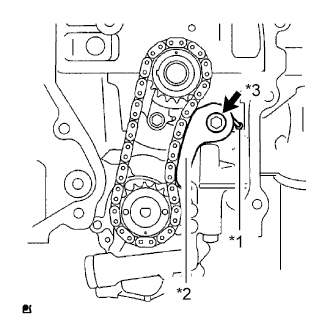
Text in Illustration *1 Spring *2 Chain Tensioner Plate *3 Bolt Insert the damper spring into the adjusting hole, and then install the chain tensioner plate with the bolt.
- Torque:
- 12 N*m { 122 kgf*cm, 9 ft.*lbf }
-
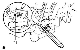
Text in Illustration *1 Groove Align the adjusting hole of the oil pump drive shaft gear with the groove of the oil pump.
-
Insert a 4 mm diameter bar into the adjusting hole of the oil pump drive shaft gear to lock the gear in position, and then tighten the nut.
- Torque:
- 30 N*m { 306 kgf*cm, 22 ft.*lbf }
-
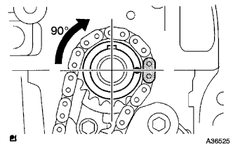
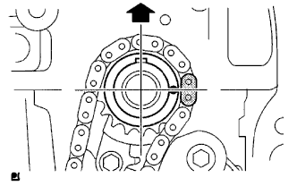
Rotate the crankshaft 90° clockwise, and position the crankshaft key to face up as shown in the illustration.
-
-
INSTALL CRANKSHAFT TIMING GEAR OR SPROCKET
-
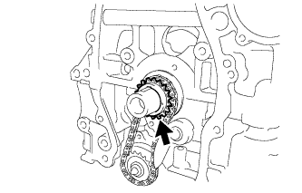
Install the crankshaft timing gear or sprocket to the crankshaft.
-
-
INSTALL NO. 1 CHAIN VIBRATION DAMPER
-
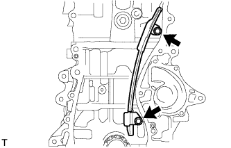
Install the No. 1 chain vibration damper with the 2 bolts.
- Torque:
- 9.0 N*m { 92 kgf*cm, 80 in.*lbf }
-
-
INSTALL CHAIN SUB-ASSEMBLY
-
Set the No. 1 cylinder to TDC/compression.
-
Text in Illustration *1 Timing Mark Turn the camshafts with a wrench (using the hexagonal lobe) to align the timing marks on the camshaft timing gear with the timing marks located on the No. 1 and No. 2 bearing caps as shown in the illustration.
-
Using the crankshaft pulley bolt, turn the crankshaft to position the key on the crankshaft upward.
-
-
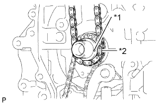
Text in Illustration *1 Timing Mark *2 Mark Link Install the chain onto the crankshaft timing sprocket with the gold or orange mark link aligned with the timing mark on the crankshaft.
-
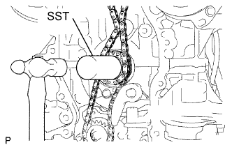
Using SST and a hammer, tap in the crankshaft timing sprocket.
- SST
- 09309-37010
-
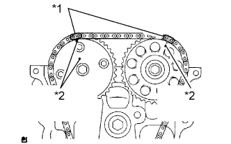
Text in Illustration *1 Mark Link *2 Timing Mark Align the gold or yellow links with the timing marks located on the camshaft timing gear and sprocket, then install the chain.
-
-
INSTALL CHAIN TENSIONER SLIPPER
-
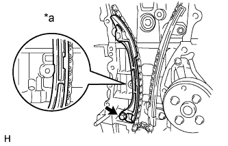
Text in Illustration *a Hold Install the chain tensioner slipper with the bolt.
- Torque:
- 19 N*m { 194 kgf*cm, 14 ft.*lbf }
-
-
INSTALL TIMING CHAIN GUIDE
-
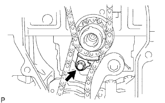
Install the timing chain guide with the bolt.
- Torque:
- 9.0 N*m { 92 kgf*cm, 80 in.*lbf }
-
-
INSTALL NO. 1 CRANKSHAFT POSITION SENSOR PLATE
-
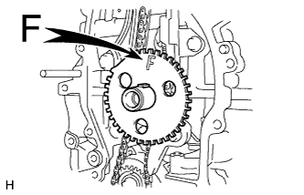
Install the sensor plate with the "F" mark facing forward.
-
-
INSTALL TIMING CHAIN COVER OIL SEAL
-
Apply MP grease to the lip of a new front crankshaft oil seal.
-
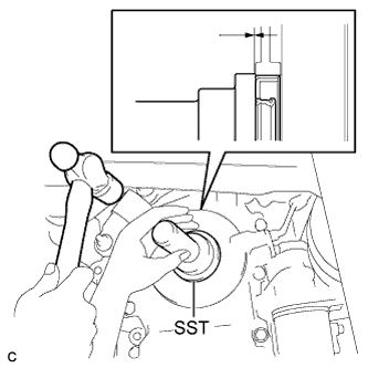
Using SST and a hammer, tap in the front crankshaft oil seal until its surface is flush with the front oil seal retainer edge.
- SST
- 09223-22010
Note
-
Keep the lip free from foreign matter.
-
Do not tap on the oil seal at an angle.
-
-
INSTALL TIMING CHAIN OR BELT COVER SUB-ASSEMBLY
-
Remove any old packing material and be careful not to drop any oil on the contact surfaces of the timing chain cover, cylinder head and cylinder block.
-
Apply seal packing (Diameter 4.0 to 4.5 mm (0.157 to 0.177 in.)) as shown in the illustration.
Text in Illustration 
Seal Packing Seal packing Toyota Genuine Seal Packing Black, Three Bond 1207B or equivalent Note
-
Remove any oil from the contact surfaces.
-
Install the chain cover within 3 minutes of applying seal packing.
-
Do not add engine oil for at least 2 hours after installing the chain cover.
-
-
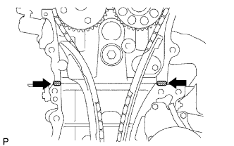
Apply a continuous bead of seal packing as shown in the illustration.
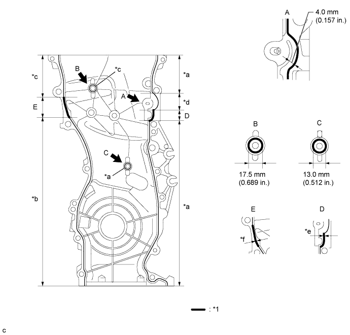
Text in Illustration *1 Seal Packing - - *a Seal Diameter: 2.5 to 3.0 mm (0.0984 to 0.118 in.) *b Seal Diameter: 3.0 mm (0.118 in.) *c Seal Diameter: 4.0 mm (0.157 in.) *d Seal Diameter: 4.0 to 4.5 mm (0.157 to 0.177 in.) *e Seal Diameter: 4.5 to 5.0 mm (0.177 to 0.197 in.) *f Seal Diameter: 5.5 to 6.0 mm (0.217 to 0.236 in.) Seal packing Toyota Genuine Seal Packing Black, Three Bond 1207B or equivalent Note
-
Remove any oil from the contact surfaces.
-
Install the chain cover within 3 minutes of applying seal packing.
-
Do not add engine oil for at least 2 hours after installing the chain cover.
-
-
Apply adhesive to the threads of the bolt A.
Seal packing Toyota Genuine Adhesive 1324, Three Bond 1324 or equivalent -
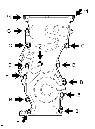
Text in Illustration *1 Nut Temporarily install the timing chain cover with the 12 bolts and 2 nuts.
Bolt Length Item Length Bolt A 30 mm (1.18 in.) length for 10 mm head Bolt B 30 mm (1.18 in.) length for 12 mm head Bolt C 40 mm (1.57 in.) length for 14 mm head -
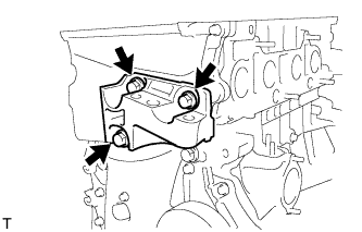
Temporarily install the engine mounting bracket RH with the 3 bolts.
-
Fully tighten the timing chain cover with the 15 bolts and 2 nuts as shown in the illustration.
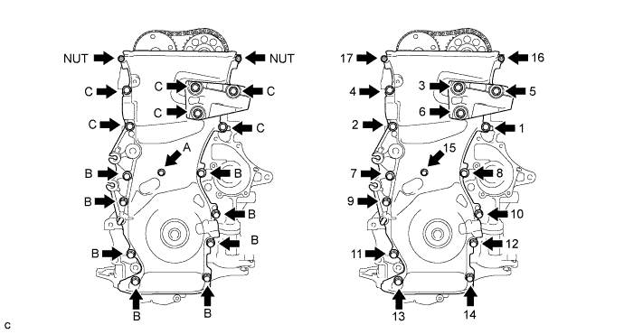
- Torque:
- Bolt A
- 9.0 N*m { 92 kgf*cm, 80 in.*lbf }
- Bolt B
- 25 N*m { 255 kgf*cm, 18 ft.*lbf }
- Bolt C
- 55 N*m { 561 kgf*cm, 41 ft.*lbf }
- Nut
- 11 N*m { 112 kgf*cm, 8 ft.*lbf }
-
Using an E10 "TORX" socket, install the stud bolt for the V-ribbed belt tensioner.
- Torque:
- 22 N*m { 220 kgf*cm, 16 ft.*lbf }
-
-
INSTALL NO. 1 CHAIN TENSIONER ASSEMBLY
-
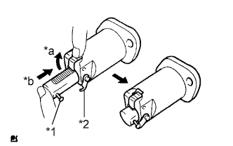
Text in Illustration *1 Pin *2 Hook *a Raise *b Push Release the ratchet pawl, then fully push in the plunger and set the hook to the pin so that the plunger is in the position shown in the illustration.
-
Install a new gasket and the chain tensioner with the 2 nuts.
Text in Illustration Engine Front - Torque:
- 9.0 N*m { 92 kgf*cm, 80 in.*lbf }
Note
When installing the chain tensioner, set the hook again if the hook releases the plunger.
-
-
INSTALL V-RIBBED BELT TENSIONER ASSEMBLY
-
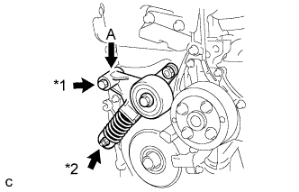
Text in Illustration *1 Bolt *2 Nut Temporarily install the V-ribbed belt tensioner assembly with the nut.
Note
Do not lift the engine more than necessary.
-
Slightly push down on the V-ribbed belt tensioner assembly at part (A) to align the holes of the engine and tensioner as shown in the illustration, and temporarily install the bolt.
-
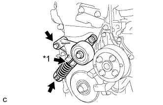
Text in Illustration *1 Pin Tighten the bolt and nut to install the V-ribbed belt tensioner.
- Torque:
- 60 N*m { 612 kgf*cm, 44 ft.*lbf }
Note
-
When replacing the V-ribbed belt tensioner with a new one, do not pull out the pin.
-
The pin will be removed in a later step.
-
-
INSTALL CRANKSHAFT PULLEY
-
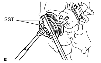
Using SST, secure the pulley in place and tighten the bolt.
- SST
- 09213-54015 ( 91651-60855 )
- 09330-00021
- Torque:
- 180 N*m { 1835 kgf*cm, 133 ft.*lbf }
-
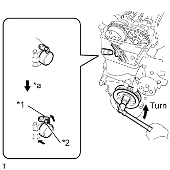
Text in Illustration *1 Hook *2 Pin *a Disconnect Turn the crankshaft counterclockwise, then disconnect the hook from the pin.
-
Text in Illustration *1 Plunger *a Extend *b Turn Turn the crankshaft clockwise, then check that the plunger is extended.
-
-
INSTALL OIL PAN SUB-ASSEMBLY
-
Remove any old packing material and be careful not to drop any oil on the contact surfaces of the cylinder block and oil pan.
-
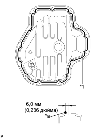
Text in Illustration *1 Seal Packing *a Seal Diameter: 3.0 to 4.0 mm Apply a continuous bead of seal packing (diameter 3.0 to 4.0 mm (0.118 to 0.157 in.)) as shown in the illustration.
Seal packing Toyota Genuine Seal Packing Black, Three Bond 1207B or equivalent Note
-
Remove any oil from the contact surfaces.
-
Install the oil pan within 3 minutes of applying seal packing.
-
Do not add engine oil for at least 2 hours after installing the oil pan.
-
-
Install the oil pan onto the cylinder block.
-
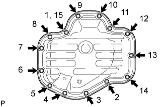
Uniformly tighten the 12 bolts and 2 nuts in the sequence shown in the illustration.
- Torque:
- 9.0 N*m { 92 kgf*cm, 80 in.*lbf }
-
-
INSTALL CRANK POSITION SENSOR (for TMC Made Engine)
-
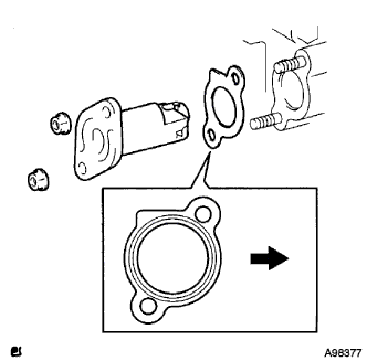
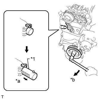
Text in Illustration *1 New O-ring Apply a light coat of engine oil to the O-ring on the crank position sensor.
-
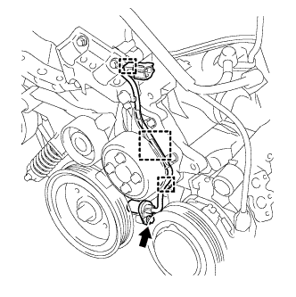
Install the crank position sensor with the bolt.
- Torque:
- 9.0 N*m { 92 kgf*cm, 80 in.*lbf }
Note
Do not twist the O-ring.
-
Install the 2 wire harness clamps.
-
Install the connector to the connector bracket.
-
-
INSTALL CRANK POSITION SENSOR (except TMC Made Engine)
-

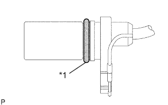
Text in Illustration *1 New O-ring Apply a light coat of engine oil to the O-ring on the crank position sensor.
-
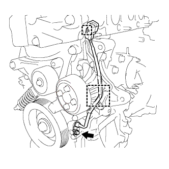
Install the crank position sensor with the bolt.
- Torque:
- 9.0 N*m { 92 kgf*cm, 80 in.*lbf }
Note
Do not twist the O-ring.
-
Install the wire harness clamp.
-
Install the connector to the connector bracket.
-
-
INSTALL IDLER PULLEY SUB-ASSEMBLY
-
Install the idler pulley bracket with the 2 bolts.
- Torque:
- 50 N*m { 510 kgf*cm, 37 ft.*lbf }
-
-
INSTALL CYLINDER HEAD COVER SUB-ASSEMBLY
-
Remove any old packing material from the contact surfaces.
-
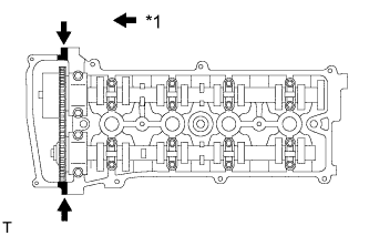
Text in Illustration *1 Seal Packing Apply seal packing to the 2 locations shown in the illustration.
Seal Packing Toyota Genuine Seal Packing Black, Three Bond 1207B or equivalent Note
-
Remove any oil from the contact surfaces.
-
Install the cylinder head cover within 3 minutes of applying seal packing.
-
Do not start the engine for at least 2 hours after installing the cylinder head cover.
-
-
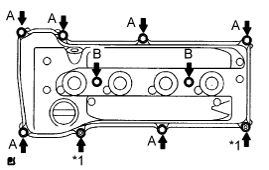
Text in Illustration *1 Nut Install the cylinder head cover with the 8 bolts and 2 nuts.
- Torque:
- Bolt A
- 11 N*m { 112 kgf*cm, 8 ft.*lbf }
- Bolt B
- 14 N*m { 143 kgf*cm, 10 ft.*lbf }
- Nut
- 11 N*m { 112 kgf*cm, 8 ft.*lbf }
-
-
INSTALL IGNITION COIL ASSEMBLY
-
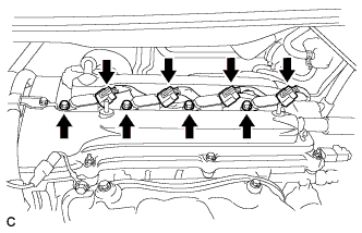
Install the 4 ignition coils with the 4 bolts.
- Torque:
- 9.0 N*m { 92 kgf*cm, 80 in.*lbf }
-
Connect the 4 ignition coil connectors.
-
-
INSTALL ENGINE HANGERS
-
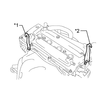
Text in Illustration *1 No. 1 Engine Hanger *2 No. 2 Engine Hanger Install the No. 1 engine hanger and No. 2 engine hanger with the 2 bolts.
- Torque:
- 38 N*m { 387 kgf*cm, 28 ft.*lbf }
Part Name Part No. No. 1 engine hanger 12281-28010 or
12281-0H010
No. 2 engine hanger 12282-28010 or
12282-0H010
Bolt 91552-B1020 or
90105-C0076
-
-
REMOVE ENGINE STAND
-
INSTALL DRIVE PLATE AND RING GEAR SUB-ASSEMBLY
-
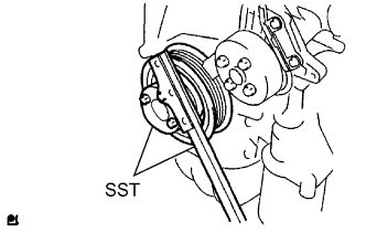
Using SST, hold the crankshaft.
- SST
- 09213-54015 ( 91651-60855 )
- 09330-00021
-
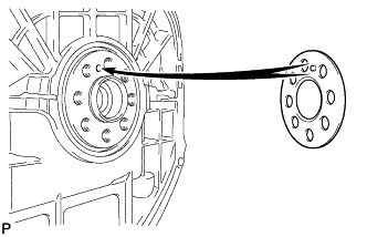
Install the front spacer.
Tech Tips
Align the pin of the front spacer with the pin hole of the crankshaft.
-
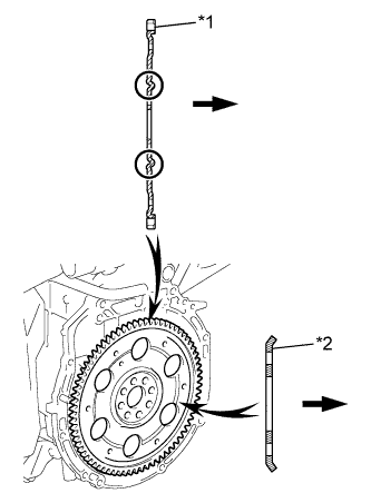
Text in Illustration *1 Drive Plate And Ring Gear Sub-Assembly *2 Rear Spacer Transaxle Install the drive plate and ring gear sub-assembly and rear spacer onto the crankshaft.
-
Clean the 8 bolts and 8 bolt holes.
-
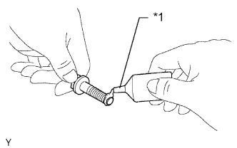
Text in Illustration *1 Adhesive Apply adhesive to 2 or 3 threads of the 8 bolts.
Adhesive Toyota Genuine Adhesive 1324, Three Bond 1324 or equivalent -
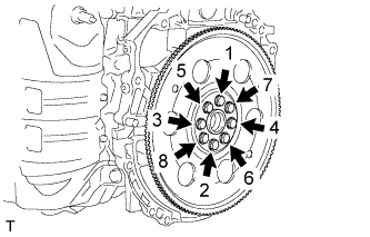
In several steps, uniformly install and tighten the 8 bolts in the sequence shown in the illustration.
- Torque:
- 98 N*m { 999 kgf*cm, 72 ft.*lbf }
Note
Do not start the engine for at least an hour after installing the drive plate.
-
-
INSTALL AUTOMATIC TRANSAXLE ASSEMBLY (for Automatic Transaxle)
-
INSTALL CONTINUOUSLY VARIABLE TRANSAXLE ASSEMBLY (for CVT)