ТОПЛИВНЫЙ БАК УСТАНОВКА
-
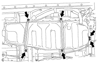
INSTALL FUEL TANK CUSHION
-
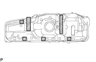
Install 6 new fuel tank cushions onto the fuel tank as shown in the illustration.
-
-
INSTALL REAR FUEL TANK BRACKET
-
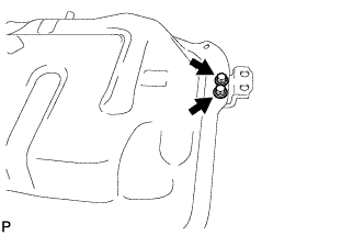
Install the rear fuel tank bracket with the 2 bolts.
- Torque:
- 42 N*m { 428 kgf*cm, 31 ft.*lbf }
-
-
INSTALL NO. 1 FUEL TANK PROTECTOR
-
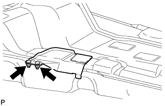
Install the protector with the 2 nuts.
- Torque:
- 6.0 N*m { 61 kgf*cm, 53 in.*lbf }
-
-
INSTALL CHARCOAL CANISTER OUTLET TUBE SUB-ASSEMBLY
-
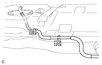
Install the 2 tube clamps to the fuel tank.
-
Install the charcoal canister outlet tube sub-assembly to the fuel tube clamps.
-
-
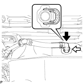
INSTALL NO. 2 FUEL EVAPORATION TUBE SUB-ASSEMBLY
-
Text in Illustration *1 Retainer *2 O-ring Push in the No. 2 fuel evaporation tube sub-assembly connector to the fuel tank until the retainer makes a "click" sound.
Note
-
Before installing the tube, make sure that it is not damaged. Make sure that there is no foreign matter present on the connecting surfaces.
-
After connecting, check if the pipe and the connector are securely connected by pulling on them.
-
-
-
INSTALL FUEL TANK MAIN TUBE SUB-ASSEMBLY
-
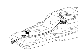
Install the 2 No. 2 fuel tube clamps to the fuel tank.
-
Install the fuel tank main tube sub-assembly to the fuel tube clamps.
-
-
INSTALL NO. 1 FUEL EVAPORATION TUBE SUB-ASSEMBLY
-
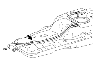
Install the No. 1 fuel evaporation tube sub-assembly to the fuel tube clamps.
-
-
INSTALL FUEL TANK ASSEMBLY
-
Set the fuel tank on a transmission jack.
-
Lift up the transmission jack.
-
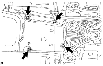
Install the fuel tank bracket and 2 fuel tank bands with the 6 bolts.
- Torque:
- 45 N*m { 459 kgf*cm, 33 ft.*lbf }
Note
First temporarily install the bolts of the tank bracket. Then temporarily install the bolts of the tank bands. Finally, tighten all of the bolts.
-
-
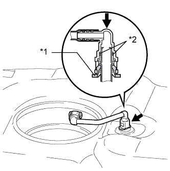
CONNECT CHARCOAL CANISTER OUTLET TUBE SUB-ASSEMBLY
-
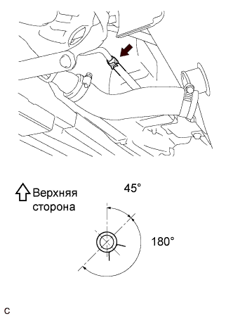
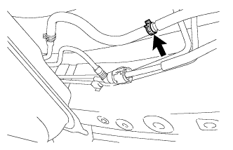
Connect the charcoal canister outlet tube sub-assembly to the filler pipe as shown in the illustration, then fit it with the clip.
-
-
CONNECT NO. 1 FUEL TANK BREATHER TUBE
-
Connect the fuel tank breather tube to the fuel tank.
Note
-
Before installing the tube, make sure that it is not damaged. Make sure that there is no foreign matter present on the connecting surfaces.
-
After connecting, check if the pipe and the connector are securely connected by pulling on them.
-
-
-
CONNECT FUEL TANK TO FILLER PIPE HOSE
-
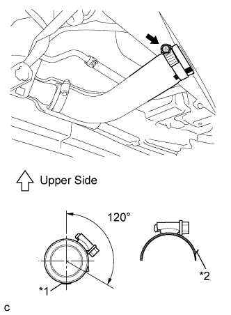
Text in Illustration *1 Mark *2 Stopper Connect the filler pipe hose to the fuel tank.
-
-
INSTALL FUEL HOSE PROTECTOR
-
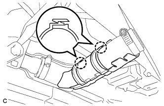
Engage the 2 claws to install the fuel hose protector onto the fuel tank to filler pipe.
-
-
CONNECT FUEL TANK MAIN TUBE SUB-ASSEMBLY
Note
Before installing the tube connector to the pipe, check the connector for damage and foreign matter.
-
Connect the fuel tank main tube sub-assembly.
-
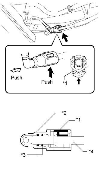
Text in Illustration *1 Retainer *2 Fuel Tube Connector *3 O-ring *4 Pipe Align the fuel tube connector with the pipe and push the fuel tube connector in until it is seated to connect the fuel tank main tube to the pipe, then push the retainer up until the claws lock.
Note
-
Check that there are no scratches or foreign matter around the connecting surfaces of the fuel tube connector and pipe before performing this work.
-
After connecting the fuel tank main tube, check that the fuel tank main tube is securely connected by pulling on the fuel tube connector and pipe.
-
-
-
-
CONNECT NO. 1 FUEL EVAPORATION TUBE SUB-ASSEMBLY
-
Connect the No. 1 fuel evaporation tube sub-assembly to the evaporation tube hose.
-
-
INSTALL FRONT FLOOR COVER LH
-
Install the floor cover with the 4 bolts.
- Torque:
- 12 N*m { 123 kgf*cm, 9 ft.*lbf }
-
-
INSTALL FUEL SUCTION TUBE ASSEMBLY WITH PUMP AND GAUGE
-
Install the fuel suction tube assembly with pump and gauge Click here.
-
-
ADD FUEL
-
INSPECT FOR FUEL LEAK
-
Check fuel pump operation.
-
Connect the intelligent tester to the DLC3.
-
Turn the engine switch on (IG) and turn the intelligent tester on.
Note
Do not start the engine.
-
Enter the following menus: Powertrain / Engine / Active Test / Control the Fuel Pump / Speed.
-
Check for pressure in the fuel inlet tube from the fuel line. Check that sounds of fuel flowing in the fuel tank can be heard. If no sounds can be heard, check the integration relay, fuel pump, ECM and wiring connectors.
-
-
Inspect for fuel leaks.
-
Check that there is no fuel leakage after performing maintenance anywhere on the fuel system. If there is a fuel leak, repair or replace parts if necessary.
-
-
Turn the engine switch off.
-
Disconnect the intelligent tester from the DLC3.
-