ДВИГАТЕЛЬ ПРОВЕРКА БЕЗ СНЯТИЯ С АВТОМОБИЛЯ

-
INSPECT ENGINE COOLANT
-
INSPECT ENGINE OIL
-
INSPECT BATTERY
-
INSPECT AIR CLEANER FILTER ELEMENT SUB-ASSEMBLY
-
Remove the air cleaner cap sub-assembly Click here.
-
Remove the air cleaner filter element.
-
Visually check that the air filter is not excessively damaged or oily.
If necessary, replace the air filter.
-
-
INSPECT SPARK PLUG
Note
-
Do not use a wire brush for cleaning.
-
Do not attempt to adjust the electrode gap of a used spark plug.
-
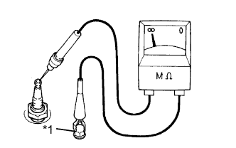
Text in Illustration *1 Ground Check the electrode.
-
Using a megohmmeter, measure the insulation resistance.
Standard Resistance 10 MΩ or more If a megohmmeter is not available, perform the following simple inspection instead.
Tech Tips
If the result is not as specified, clean the spark plug with a spark plug cleaner and measure the resistance again.
-
-
Alternative inspection method:
-
Quickly accelerate the engine to 4000 rpm 5 times.
-
Remove the spark plug Click here.
-
Visually check the spark plug.
If the electrode is dry, the spark plug is functioning properly. If the electrode is damp, proceed to the next step.
-
-
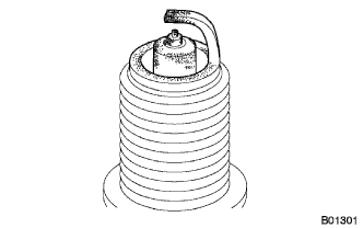
Check the spark plug for any damage to its threads and insulator.
If there is any damage, replace the spark plug.
Recommended Spark Plug Manufacturer Product DENSO SK16R11 NGK IFR5A11 -
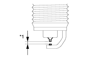
Text in Illustration *1 Electrode Gap Reference:
Maximum Electrode Gap for Used Spark Plug Electrode Gap 1.3 mm (0.0512 in.) If the electrode gap is greater than the maximum, replace the spark plug.
Electrode Gap for New Spark Plug Electrode Gap 1.0 to 1.1 mm (0.0394 to 0.0433 in.) -
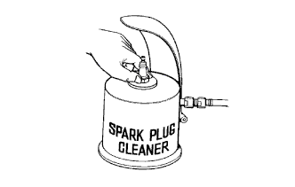
Clean the spark plug.
If the electrode has traces of wet carbon, clean the electrode with a spark plug cleaner and then dry it.
Air pressure 588 kPa (6.0 kgf/cm2, 85 psi) Duration 20 seconds or less Tech Tips
Only use the spark plug cleaner when the electrode is free of oil. If the electrode has traces of oil, use gasoline to clean off the oil before using the spark plug cleaner.
-
Install the spark plug Click here.
-
-
INSPECT V-RIBBED BELT
-
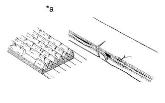
Text in Illustration *a INCORRECT Check the belt for wear, cracks or other signs of damage.
If any of the following defects is found, replace the V-ribbed belt.
-
The belt is cracked.
-
The belt is worn out to the extent that cords are exposed.
-
The belt has chunks missing from the ribs.
-
-
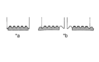
Text in Illustration *a CORRECT *b INCORRECT Check that the belt fits properly in the ribbed grooves.
Tech Tips
Check with your hand to confirm that the belt has not slipped out of the groove on the bottom of the pulley. If it has slipped out, replace the V-ribbed belt. Install a new V-ribbed belt correctly.
-
-
INSPECT IGNITION TIMING
Note
-
Turn all the electrical systems and the A/C off.
-
When checking the ignition timing, the transaxle should be in neutral or park.
-
Warm up and stop the engine.
-
When using the intelligent tester:
-
Connect the intelligent tester to the DLC3.
-
Turn the engine switch on (IG).
-
Turn the intelligent tester on.
-
Enter the following menus: Power Train / Engine and ECT / Data List / IGN Advance
-
Start the engine.
-
According to the display on the intelligent tester, read the Data List.
Standard ignition timing 8 to 16° BTDC at idle -
Check that the ignition timing advances immediately when the engine speed is increased.
-
Turn the engine switch off.
-
Disconnect the intelligent tester from the DLC3.
-
-
When not using the intelligent tester:
-
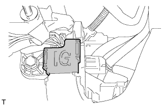
Open the ignition cover located to the right of the No. 4 ignition coil.
-
Pull the wire harness out from the IG cover.
-
Connect the timing light to the wire harness.
Note
Use a timing light that detects the primary signal.
-
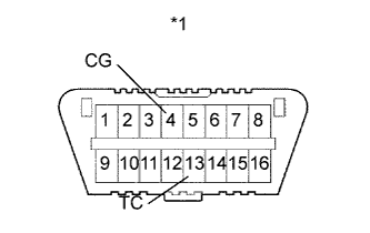
Text in Illustration *1 DLC3 Using SST, connect terminals 13 (TC) and 4 (CG) of the DLC3.
- SST
- 09843-18040
-
Allow the engine to idle and check the ignition timing.
Standard ignition timing 8 to 12° BTDC at idle Tech Tips
Run the engine at 1000 to 1300 rpm for 5 seconds, then check that the engine speed returns to idle speed.
-
Disconnect SST from terminals 13 (TC) and 4 (CG) of the DLC3.
-
Allow the engine to idle and check the ignition timing.
Standard ignition timing 8 to 16° BTDC at idle -
Check that the ignition timing advances immediately when the engine speed is increased.
-
Turn the engine switch off.
-
Remove the timing light.
-
Close the IG cover.
-
-
-
INSPECT ENGINE IDLE SPEED
Note
-
Turn all the electrical systems and the A/C off.
-
When checking the idle speed, the transaxle should be in neutral or park.
-
Warm up and stop the engine.
-
When using the intelligent tester:
-
Connect the intelligent tester to the DLC3.
-
Turn the engine switch on (IG).
-
Turn the intelligent tester on.
-
Enter the following menus: Power Train / Engine and ECT / Data List / Engine Speed
-
Start the engine.
-
According to the display on the intelligent tester, read the Data List.
Standard idle speed 670 to 770 rpm -
Turn the engine switch off.
-
Disconnect the intelligent tester from the DLC3.
-
-
When not using the intelligent tester:
-
Turn off all the accessories and air conditioning.
-
Move the shift lever to P or N.
-
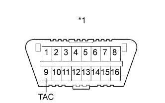
Text in Illustration *1 DLC3 Connect SST to 9 (TAC) of the DLC3 terminal, and then connect a tachometer to SST.
- SST
- 09843-18030
-
Start the engine.
-
Check the idle speed with the cooling fans off.
Standard idle speed 670 to 770 rpm -
Turn the engine switch off.
-
Remove the tachometer and disconnect SST from the DLC3.
-
-
-
INSPECT COMPRESSION
-
Warm up and stop the engine.
-
Remove the 4 ignition coils and spark plugs Click here.
-
Disconnect the 4 fuel injector connectors.
-
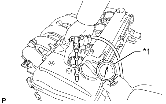
Text in Illustration *1 Compression Gauge Insert a compression gauge into the spark plug hole.
-
Fully open the throttle.
-
While cranking the engine, measure the compression pressure.
Standard compression pressure 1300 kPa (13.3 kgf/cm2, 189 psi) Minimum compression pressure 1000 kPa (10.0 kgf/cm2, 145 psi) Standard difference between each cylinder 100 kPa (1.0 kgf/cm2, 15 psi) or less Note
-
Always use a fully-charged battery to obtain an engine speed of 250 rpm or more.
-
Check the other cylinders in the same way.
-
This measurement must be done as quickly as possible.
If the cylinder compression is low, pour a small amount of engine oil into the cylinder through the spark plug hole and inspect it again.
Tech Tips
-
If adding oil increases the compression, the piston rings and/or cylinder bore may be worn or damaged.
-
If pressure stays low, a valve may be stuck or seated improperly, or there may be leakage in the gasket.
-
-
Connect the 4 fuel injector connectors.
-
Install the 4 spark plugs and ignition coils Click here.
-
-
INSPECT CO/HC
Tech Tips
This check determines whether or not the idle CO/HC complies with local regulations.
-
Start and warm up the engine.
-
Run the engine at 2500 rpm for approximately 180 seconds.
-
Insert the CO/HC meter testing probe at least 40 cm (1.3 ft.) into the tailpipe while idling.
-
Inspect the CO/HC concentration during idle at 2500 rpm.
If the CO/HC concentration does not comply with local regulations, troubleshoot in the order given below.
-
Check the A/F sensor and heated oxygen sensor operation.
-
See the table below for possible causes, then inspect the applicable parts and repair them if necessary.
CO HC Problem Possible Cause Normal High Rough idle 1. Faulty ignition:
- Incorrect timing
- Plugs are contaminated, shorted, or gaps are defective
2. Incorrect valve clearance
3. Leaks in intake and exhaust valve
4. Leaks in cylinders
Low High Rough idle
(Fluctuating HC reading)
1. Vacuum leakage:
- Ventilation hoses
- Intake manifold
- Throttle body
- Brake booster line
2. Lean mixture causing misfire
High High Rough idle
(Black smoke from exhaust)
1. Restricted air filter
2. Plugged PCV valve
3. Faulty EFI system:
- Faulty pressure regulator
- Faulty engine coolant temperature sensor
- Faulty mass air flow meter
- Faulty ECM
- Faulty injectors
- Faulty throttle body
-
-