БЛОК ДВИГАТЕЛЯ РАЗБОРКА

Tech Tips
Check whether the engine is TMC made or not by referring to the following illustration.
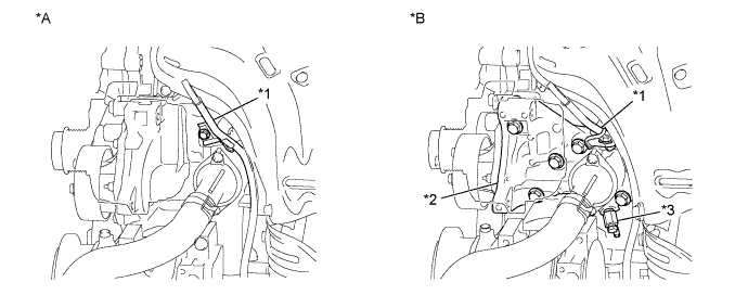
| *A | for TMC Made Engine | *B | except TMC Made Engine |
| *1 | Engine Oil Level Dipstick Guide | *2 | Water Inlet Housing |
| *3 | Water Inlet Housing Drain Cock Assembly | - | - |
-
REMOVE OIL FILLER CAP SUB-ASSEMBLY
-
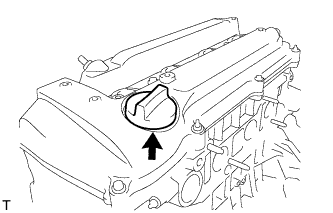
Remove the oil filler cap from the cylinder head cover.
-
-
REMOVE OIL FILLER CAP GASKET
-
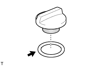
Remove the oil filler cap gasket from the oil filler cap.
-
-
REMOVE VENTILATION VALVE SUB-ASSEMBLY
-
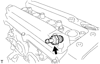
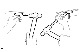
Using a 22 mm deep socket wrench, remove the ventilation valve from the cylinder head cover.
-
-
REMOVE SPARK PLUG
-
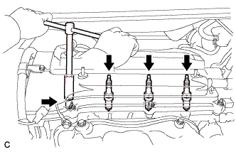
Remove the 4 spark plugs.
-
-
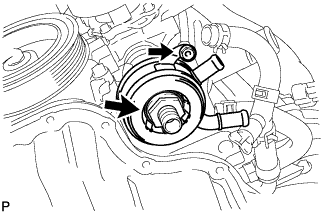
REMOVE OIL FILTER SUB-ASSEMBLY
-
Using SST, remove the oil filter sub-assembly.
- SST
- 09228-06501
-
-
REMOVE ENGINE OIL COOLER (for TMC Made Engine with Engine Oil Cooler)
-
Remove the nut, oil cooler union and oil cooler.
-
-
REMOVE OIL FILTER UNION (except TMC Made Engine with Engine Oil Cooler)
-
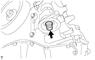
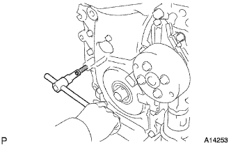
Using a 12 mm socket hexagon wrench, remove the oil filter union.
-
-
REMOVE CYLINDER HEAD COVER SUB-ASSEMBLY
-
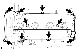
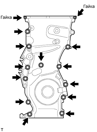
Text in Illustration *1 Nut Remove the 8 bolts and 2 nuts, and remove the cylinder head cover.
-
-
REMOVE CYLINDER HEAD COVER GASKET
-
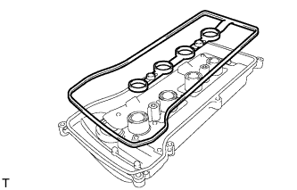
Remove the cylinder head cover gasket from the cylinder head cover.
-
-
REMOVE ENGINE MOUNTING BRACKET RH
-
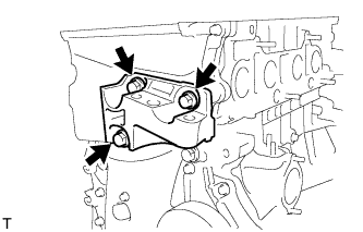
Remove the 3 bolts and engine mounting bracket RH.
-
-
REMOVE V-RIBBED BELT TENSIONER ASSEMBLY
-
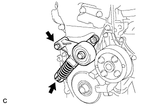
Remove the bolt, nut and belt tensioner.
-
-
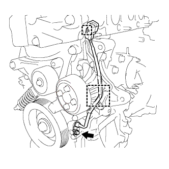
REMOVE CRANK POSITION SENSOR (for TMC Made Engine)
-
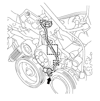
Disconnect the connector from the connector bracket.
-
Disconnect the 2 wire harness clamps.
-
Remove the bolt and crank position sensor.
-
-
REMOVE CRANK POSITION SENSOR (except TMC Made Engine)
-
Disconnect the connector from the connector bracket.
-
Disconnect the wire harness clamp.
-
Remove the bolt and crank position sensor.
-
-
REMOVE CAMSHAFT POSITION SENSOR
-
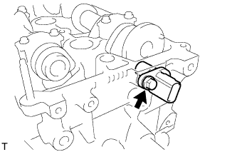
Remove the bolt and camshaft position sensor.
-
-
SET NO. 1 CYLINDER TO TDC/COMPRESSION
-
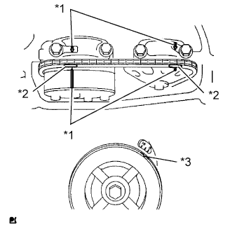
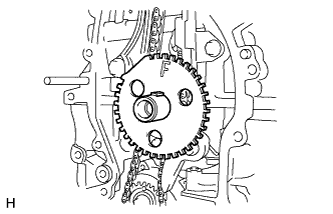
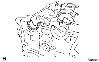
Text in Illustration *1 Timing Mark *2 Paint Mark *3 Groove Turn the crankshaft pulley until the groove and the timing mark "0" on the timing chain cover are aligned.
-
Check that each timing mark on the camshaft timing gear and sprocket is aligned with each timing mark located on the No. 1 and No. 2 bearing caps as shown in the illustration.
If not, turn the crankshaft pulley 1 revolution (360°) to align the timing marks as illustrated.
-
Place paint marks on the chain in alignment with the timing marks on the camshaft timing gear and camshaft timing sprocket.
-
-
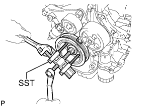
REMOVE CRANKSHAFT PULLEY
-
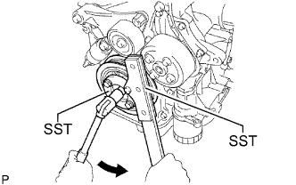
Using SST, hold the crankshaft pulley in place and loosen the pulley bolt.
- SST
- 09213-54015 ( 91651-60855 )
- 09330-00021
-
Using SST, remove the crankshaft pulley.
- SST
- 09950-50013 ( 09951-05010, 09952-05010, 09953-05020, 09954-05021 )
- 09950-40011 ( 09957-04010 )
Tech Tips
If necessary, remove the pulley and pulley bolt using SST.
-
-
REMOVE CAMSHAFT TIMING OIL CONTROL VALVE ASSEMBLY
-
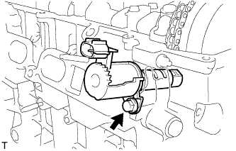
Remove the bolt and camshaft timing oil control valve from the cylinder head.
Note
The camshaft timing oil control valve may be damaged when loosening the cylinder head bolts if it is not removed.
-
Remove the O-ring from the camshaft timing oil control valve.
-
-
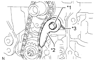
REMOVE NO. 1 CHAIN TENSIONER ASSEMBLY
-
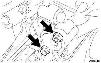
Remove the 2 nuts, No. 1 chain tensioner assembly and gasket.
Note
Do not turn the crankshaft without the No. 1 chain tensioner assembly.
-
-
REMOVE WATER PUMP PULLEY
-
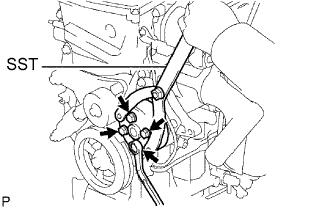
Using SST, remove the 4 bolts and water pump pulley.
- SST
- 09960-10010 ( 09962-01000, 09963-00700 )
-
-
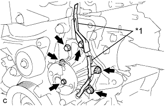
REMOVE WATER PUMP ASSEMBLY (for TMC Made Engine)
-
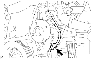
Remove the clamp of the crankshaft position sensor from the water pump.
-
Disconnect the wire of the crankshaft position sensor from the clamp bracket.
-
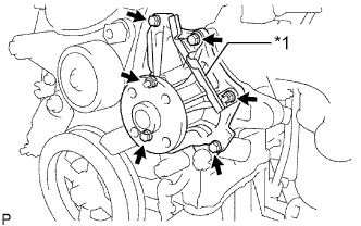
Text in Illustration *1 Clamp Bracket Remove the 4 bolts, 2 nuts and clamp bracket.
-
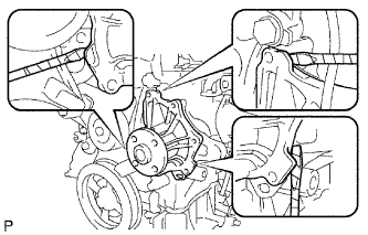
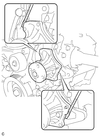
Using a screwdriver, pry between the water pump and cylinder block, and then remove the water pump.
Tech Tips
Tape the screwdriver tip before use.
Note
Be careful not to damage the contact surfaces of the water pump and cylinder block.
-
-
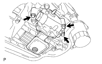
REMOVE WATER PUMP ASSEMBLY (except TMC Made Engine)
-
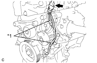
Text in Illustration *1 Clamp Bracket Disconnect the connector of the crankshaft position sensor.
-
Disconnect the wire of the crankshaft position sensor from the clamp brackets.
-
Text in Illustration *1 Clamp Bracket Remove the 4 bolts, 2 nuts and 2 clamp brackets.
-
Using a screwdriver, pry between the water pump and cylinder block, and then remove the water pump.
Tech Tips
Tape the screwdriver tip before use.
Note
Be careful not to damage the contact surfaces of the water pump and cylinder block.
-
-
REMOVE OIL PAN DRAIN PLUG
-
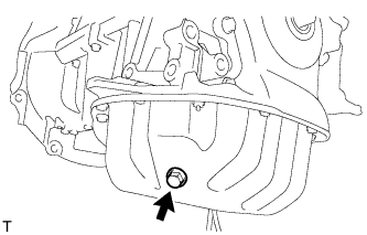
Remove the oil pan drain plug and gasket from the oil pan.
-
-
REMOVE OIL PAN SUB-ASSEMBLY
-
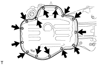
Remove the 12 bolts and 2 nuts.
-
Insert the blade of an oil pan seal cutter between the crankcase, chain cover and oil pan, then cut through the applied sealer and remove the oil pan.
Note
Be careful not to damage the contact surfaces of the crankcase, chain cover or oil pan.
-
-
REMOVE TIMING CHAIN COVER SUB-ASSEMBLY
-
Remove the 3 bolts and engine mounting bracket RH.
-
Using an E10 "TORX" socket, remove the stud bolt for the V-ribbed belt tensioner.
-
Remove the 12 bolts and 2 nuts.
-
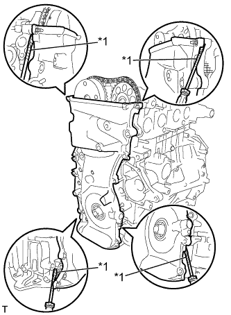
Text in Illustration *1 Protective Tape Remove the timing chain cover by prying the portions between the timing chain cover, cylinder head and cylinder block with a screwdriver.
Note
Be careful not to damage the contact surfaces of the timing chain cover, cylinder head or cylinder block.
Tech Tips
Tape the screwdriver tip before use.
-
-
REMOVE FRONT CRANKSHAFT OIL SEAL
-
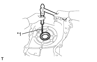
Text in Illustration *1 Protective Tape Place the timing chain cover on wooden blocks.
-
Using a screwdriver, pry out the oil seal.
Note
Do not damage the surface of the oil seal press fit hole.
Tech Tips
Tape the screwdriver tip before use.
-
-
REMOVE NO. 1 CRANKSHAFT POSITION SENSOR PLATE
-
Remove the No. 1 crankshaft position sensor plate.
-
-
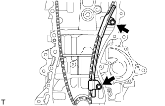
REMOVE TIMING CHAIN GUIDE
-
Remove the bolt and timing chain guide.
-
-
REMOVE CHAIN TENSIONER SLIPPER
-
Remove the bolt and chain tensioner slipper.
-
-
REMOVE NO. 1 CHAIN VIBRATION DAMPER
-
Remove the 2 bolts and No. 1 chain vibration damper.
-
-
REMOVE CHAIN SUB-ASSEMBLY
-
Remove the chain sub-assembly.
-
-
REMOVE CRANKSHAFT TIMING SPROCKET
-
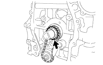
Remove the crankshaft timing gear or sprocket from the crankshaft.
-
-
REMOVE NO. 2 CHAIN SUB-ASSEMBLY
-
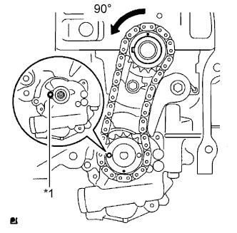
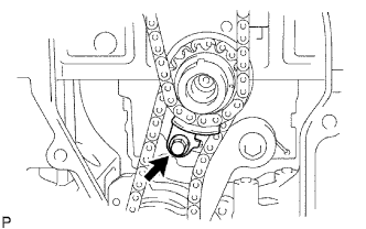
Text in Illustration *1 Groove Turn the crankshaft 90° counterclockwise to align the adjusting hole on the oil pump drive shaft sprocket with the groove on the oil pump.
-
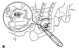
Text in Illustration *1 Groove Insert a 4 mm diameter bar into the adjusting hole of the oil pump drive shaft sprocket to lock the gear in position, and then remove the nut.
-
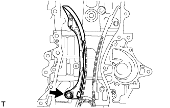
Text in Illustration *1 Bolt *2 Chain Tensioner Plate *3 Spring Remove the bolt, chain tensioner plate and spring.
-
Remove the oil pump drive sprocket, oil pump drive shaft sprocket and No. 2 chain.
-
-
REMOVE KEYS
-
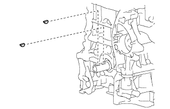
Remove the 2 pulley set keys from the crankshaft.
-
-
REMOVE NO. 2 CAMSHAFT
-
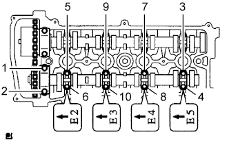
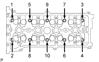
Using several steps, uniformly loosen and remove the 10 bearing cap bolts in the sequence shown in the illustration.
Note
Uniformly loosen the bolts while keeping the camshaft level.
Tech Tips
Arrange the removed parts in the correct order.
-
Remove the 5 bearing caps.
-
Remove the No. 2 camshaft.
-
-
REMOVE CAMSHAFT
-

Using several steps, uniformly loosen and remove the 10 bearing cap bolts in the sequence shown in the illustration.
Note
Uniformly loosen the bolts while keeping the camshaft level.
Tech Tips
Arrange the removed parts in the correct order.
-
Remove the 5 bearing caps.
-
Remove the camshaft.
-
-
REMOVE NO. 1 CAMSHAFT BEARING
-
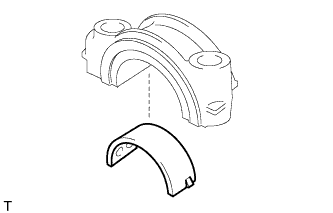
Remove the camshaft bearing from the No. 1 camshaft bearing cap.
-
-
REMOVE NO. 2 CAMSHAFT BEARING
-
Remove the No. 2 camshaft bearing from the cylinder head.
-
-
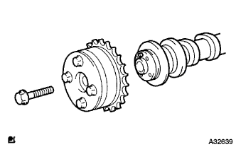
REMOVE NO. 2 CAMSHAFT TIMING SPROCKET
-
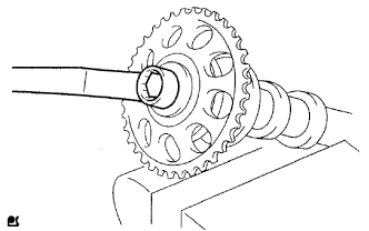
Clamp the camshaft in a vise.
Note
-
Do not overtighten the vise.
-
Do not damage the camshaft.
-
-
Remove the bolt and camshaft timing gear or sprocket.
-
-
REMOVE CAMSHAFT TIMING GEAR ASSEMBLY
-
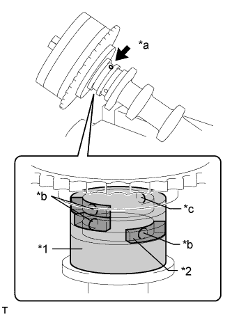
Text in Illustration *1 Vinyl Tape *2 Rubber *a Advance Side Path *b Close *c Open Clamp the camshaft in a vise, and make sure that the camshaft timing gear assembly does not rotate.
-
Cover all the oil path with vinyl tape except the advance side path shown in the illustration.
-
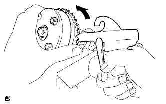
Apply air pressure of 150 kPa (1.5 kgf/cm2, 22 psi) to the oil path, then turn the camshaft timing gear assembly to the advance direction (counterclockwise) by hand.
CAUTION:
Cover the paths with a piece of cloth to avoid oil splashes.
Tech Tips
Depending on the air pressure, the camshaft timing gear assembly may turn to the advance side without applying force by hand. Also, if the pressure is difficult to apply because of air leakage from a path, the lock pin may be difficult to release.
-
Remove the flange bolt and camshaft timing gear.
Note
-
Be sure not to remove the other 4 bolts.
-
When reusing the camshaft timing gear, release the straight pin lock first, then install the gear.
-
-
-
REMOVE CYLINDER HEAD SUB-ASSEMBLY
-
In several steps, uniformly loosen and remove the 10 cylinder head bolts and 10 plate washers with a 10 mm bi-hexagon wrench in the sequence shown in the illustration.
Note
Head warpage or cracking could result from removing the bolts in the wrong order.
-
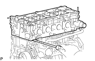
Using a screwdriver with its tip wrapped with tape, pry between the cylinder head and cylinder block, and remove the cylinder head.
Note
Be careful not to damage the contact surfaces between the cylinder head and cylinder block.
-
-
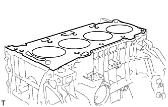
REMOVE CYLINDER HEAD GASKET
-
REMOVE CYLINDER BLOCK WATER JACKET SPACER (for TMC Made Engine)
-
Using needle nose pliers, remove the cylinder block water jacket spacer from the water jacket.
Note
Before turning the cylinder block upside down, make sure that the water jacket spacer is removed, as it will fall out.
-
-
REMOVE CYLINDER BLOCK WATER JACKET SPACER (except TMC Made Engine)
-
Using needle nose pliers, remove the cylinder block water jacket spacer from the water jacket.
Note
Before turning the cylinder block upside down, make sure that the water jacket spacer is removed, as it will fall out.
-
-
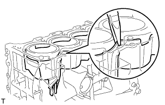
REMOVE CYLINDER BLOCK WATER DRAIN COCK SUB-ASSEMBLY (for TMC Made Engine without Engine Oil Cooler)
-
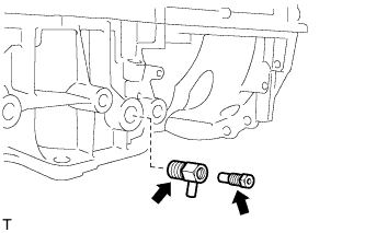
Remove the water drain cock plug from the water drain cock.
-
Remove the water drain cock from the stiffening crankcase.
-
-
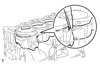
REMOVE WATER INLET HOUSING DRAIN COCK ASSEMBLY (except TMC Made Engine)
-
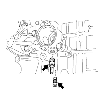
Remove the water drain cock plug from the water drain cock.
-
Remove the water inlet housing drain cock from the stiffening crankcase.
-
-
REMOVE WATER INLET HOUSING (except TMC Made Engine)
-
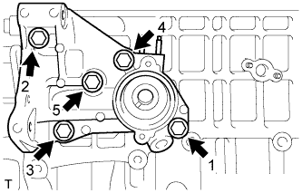
Uniformly loosen and remove the 5 bolts in the sequence shown in the illustration.
-
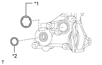
Text in Illustration *1 Water Inlet Housing O-ring *2 Water Inlet Housing Gasket Remove the water inlet housing O-ring and water inlet housing gasket from the water inlet housing.
-
-
REMOVE OIL CONTROL VALVE FILTER
-
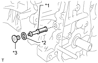
Text in Illustration *1 Oil Filter Control Valve *2 Gasket *3 Plug Using an 8 mm socket hexagon wrench, remove the plug, gasket and oil control valve filter.
-
-
REMOVE OIL PUMP ASSEMBLY
-
Remove the 3 bolts, oil pump and gasket.
-
-
INSPECT BALANCESHAFT THRUST CLEARANCE
-
Install the balanceshafts Click here.
-
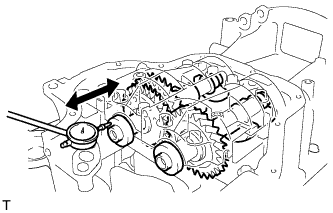
Using a dial indicator, measure the thrust clearance while moving the balanceshaft back and forth.
Standard thrust clearance 0.05 to 0.09 mm (0.00197 to 0.00354 in.) Maximum thrust clearance 0.09 mm (0.00354 in.) If the thrust clearance is greater than the maximum, replace the balanceshaft housing and bearings. If necessary, replace the balanceshaft.
-
-
REMOVE BALANCESHAFT HOUSING
-
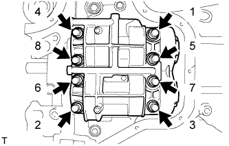
Using several steps, uniformly loosen and remove the 8 bolts in the sequence shown in the illustration.
-
Remove the balanceshaft housing from the crankcase.
Tech Tips
Keep the lower bearing and balanceshaft housing together.
-
-
REMOVE NO. 1 AND NO. 2 BALANCESHAFTS
-
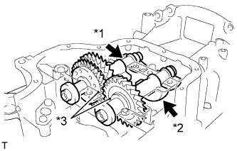
Text in Illustration *1 No. 1 *2 No. 2 *3 Timing Mark Remove the No. 1 and No. 2 balanceshafts.
-
-
REMOVE NO. 1 BALANCESHAFT BEARING
-
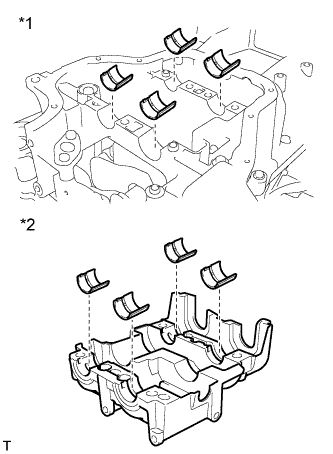
Text in Illustration *1 Stiffening Crankcase *2 Balance Shaft Housing Remove the 8 No. 1 balanceshaft bearings shown in the illustration.
-
-
INSPECT BALANCESHAFT OIL CLEARANCE
-
Clean each bearing and journal.
-
Check each bearing and journal for pitting and scratches.
If a bearing or journal is damaged, replace the bearings. If necessary, replace the balanceshaft.
-
Place the No. 1 and No. 2 balanceshafts onto the crankcase.
-
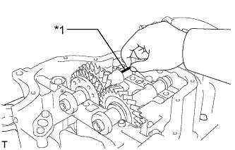
Text in Illustration *1 Plastigage Lay a strip of Plastigage across each journal.
-
Install the balanceshaft housing Click here.
Note
Do not turn the balanceshafts.
-
Remove the balanceshafts Click here.
-
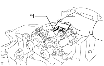
Text in Illustration *1 Plastigage Measure the Plastigage at its widest point.
Standard oil clearance 0.022 to 0.049 mm (0.000866 to 0.00193 in.) Maximum oil clearance 0.049 mm (0.00193 in.) Note
Remove the Plastigage completely after the measurement.
If the oil clearance is greater than the maximum, replace the bearing. If necessary, replace the balanceshaft.
-
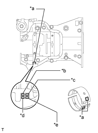
Text in Illustration *a Number Mark *b Front No. 1 Journal Bore *c Rear No. 1 Journal Bore *d Front No. 2 Journal Bore *e Rear No. 2 Journal Bore If replacing a bearing, select a new one with the same number.
Standard Balanceshaft Housing Journal Bore Diameter Item Specified Condition Mark 1 26.000 to 26.006 mm (1.0236 to 1.0239 in.) Mark 2 26.007 to 26.012 mm (1.0239 to 1.0241 in.) Mark 3 26.013 to 26.018 mm (1.0241 to 1.0243 in.) Standard Bearing Center Wall Thickness Item Specified Condition Mark 1 1.486 to 1.489 mm (0.05850 to 0.05862 in.) Mark 2 1.490 to 1.492 mm (0.05866 to 0.05874 in.) Mark 3 1.493 to 1.495 mm (0.0588 to 0.0589 in.) Standard balanceshaft journal diameter 22.985 to 23.000 mm (0.9049 to 0.9055 in.) -
Inspect the balanceshaft housing bolts.
-
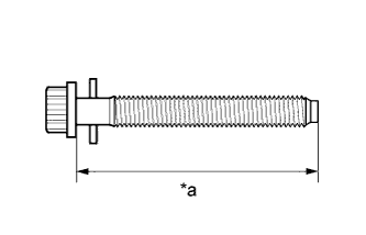
Text in Illustration *a Measurement Length Using a vernier caliper, measure the length of the bolts from the seat to the end.
Standard bolt length 58.3 to 59.7 mm (2.295 to 2.350 in.) Maximum bolt length 60.3 mm (2.374 in.) If the bolt length is greater than the maximum, replace the balanceshaft housing bolt.
-
-
-
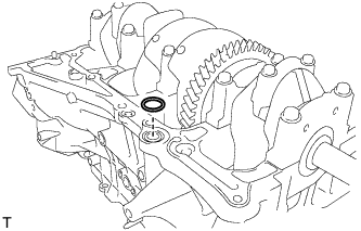
REMOVE REAR CRANKSHAFT OIL SEAL
-
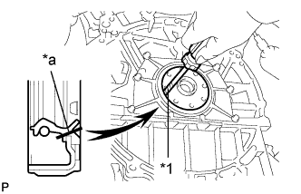
Text in Illustration *1 Protective Tape *a Cut Position Using a knife, cut off the lip of the oil seal.
-
Using a screwdriver, pry out the oil seal.
Note
After removing, check the crankshaft for damage. If damaged, smooth the surface with 400-grit sandpaper.
Tech Tips
Tape the screwdriver tip before use.
-
-
REMOVE STIFFENING CRANKCASE ASSEMBLY
-
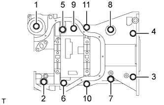
Uniformly loosen and remove the 11 bolts in the sequence shown in the illustration.
-
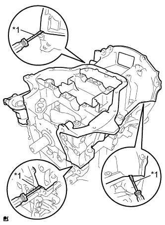
Text in Illustration *1 Protective Tape Using a screwdriver with its tip wrapped with protective tape, remove the crankcase by prying between the crankcase and cylinder block.
Note
Be careful not to damage the contact surfaces between the crankcase and cylinder block.
-
Remove the O-ring from the cylinder block.
-