БЛОК ДВИГАТЕЛЯ СНЯТИЕ
Tech Tips
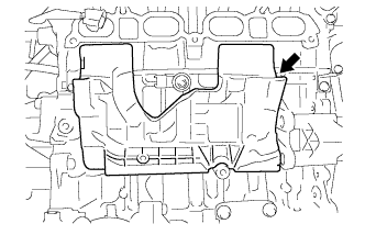
Check whether the engine is TMC made or not by referring to the following illustration.
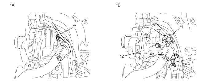
| *A | for TMC Made Engine | *B | except TMC Made Engine |
| *1 | Engine Oil Level Dipstick Guide | *2 | Water Inlet Housing |
| *3 | Water Inlet Housing Drain Cock Assembly | - | - |
-
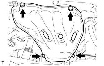
REMOVE ENGINE HANGERS
-
Remove the 2 bolts, No. 1 engine hanger and No. 2 engine hanger.
-
-
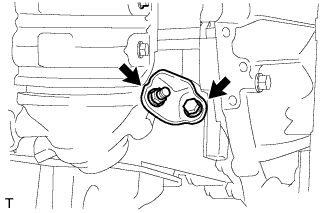
REMOVE DRIVE SHAFT BEARING BRACKET
-
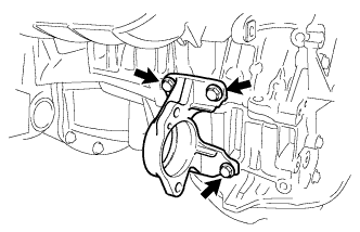
Remove the 3 bolts and drive shaft bearing bracket.
-
-
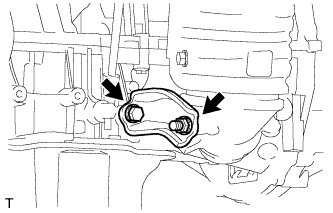
REMOVE IDLER PULLEY BRACKET
-
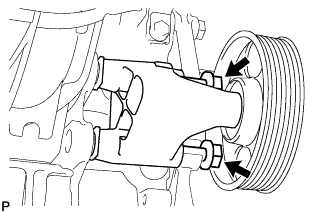
Remove the 2 bolts and idler pulley bracket.
-
-
REMOVE ENGINE WIRE
-
Remove the engine wire.
-
-
REMOVE THROTTLE BODY ASSEMBLY
-
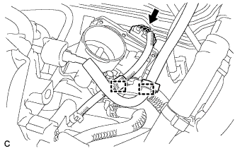
Отсоедините разъем корпуса дроссельной заслонки и зажим жгута проводов.
-
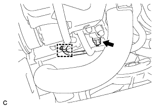
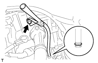
Отсоедините зажим топливного шланга от кронштейна опоры топливопровода.
-
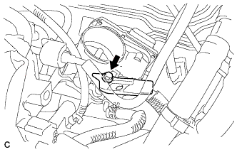
Выверните болт и снимите кронштейн опоры топливопровода.
-
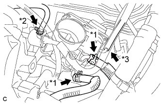
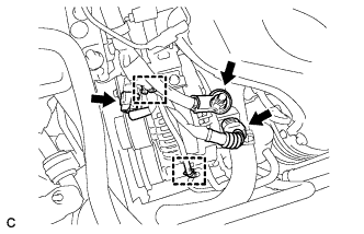
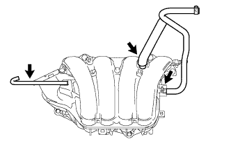
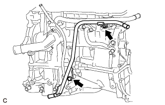
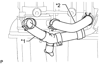
Отсоедините 2 перепускных шланга охлаждающей жидкости. (*1)
-
Отсоедините продувочный шланг. (*2)
-
Отсоедините шланг корпуса дроссельной заслонки № 1. (*3)
-
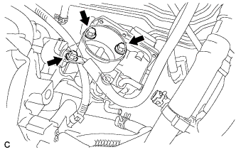
Выверните 3 болта и снимите корпус дроссельной заслонки в сборе.
-
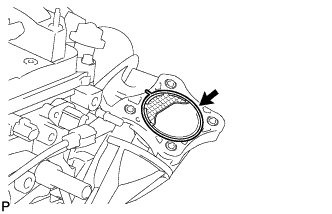
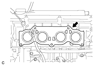
Снимите прокладку с впускного коллектора.
-
-
REMOVE FUEL DELIVERY PIPE SUB-ASSEMBLY
-
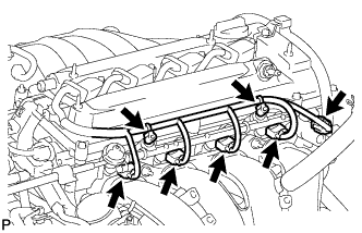
Remove the 2 wire harness clamps.
-
Disconnect the 4 fuel injector connectors.
-
Disconnect the oil control valve connector.
-
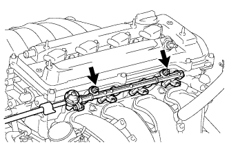
Remove the 2 bolts, then remove the fuel delivery pipe together with the 4 fuel injectors.
Note
Be careful not to drop the fuel injectors when removing the fuel delivery pipe.
-
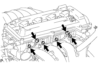
Remove the 2 delivery pipe spacers from the cylinder head.
-
Remove the 4 insulators from the cylinder head.
-
-
REMOVE FUEL INJECTOR ASSEMBLY
-
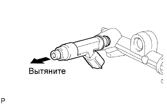
Pull out the 4 injectors from the delivery pipe.
-
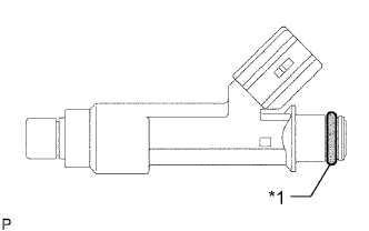
Text in Illustration *1 O-ring Remove the O-ring from each injector.
-
-
DISCONNECT NO. 2 VENTILATION HOSE
-
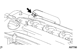
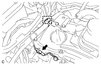
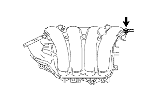
Disconnect the No. 2 ventilation hose from the ventilation valve.
-
-
REMOVE INTAKE MANIFOLD
-
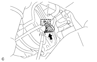
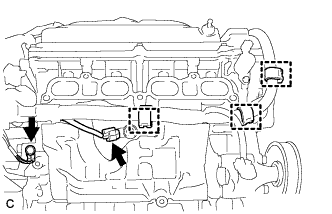
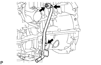
Disconnect the oxygen sensor connector and clamp.
-
Disconnect the union to check valve hose from the hose clamp.
-
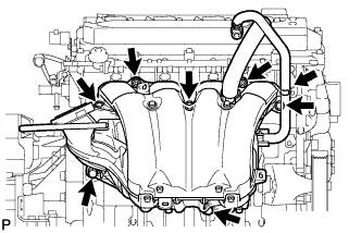
Remove the 5 bolts and 2 nuts, and separate the intake manifold.
-
Using an E7 "TORX" wrench, remove the 2 stud bolts.
-
Disconnect the engine wire.
-
Disconnect the compressor connector and clamp.
-
Disconnect the 2 connectors and 2 wire harness clamps.
-
Remove the terminal cap and nut, and disconnect the terminal B.
-
Disconnect the earth connector and wire harness clamp.
-
Disconnect the connector and 3 wire harness clamps.
-
Remove the earth bolt.
-
Disconnect the 4 connectors.
-
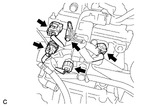
Disconnect the 4 connectors.
-
Remove the earth bolt.
-
Disconnect the connector and wire harness clamp.
-
Remove the 2 bolts and disconnect the engine wire harness.
-
-
Remove the No. 1 intake manifold insulator.
-
Remove the intake manifold.
-
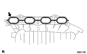
Remove the No. 1 intake manifold to head gasket.
-
Remove the union to check valve hose, No. 2 ventilation hose and No. 1 throttle body hose.
-
Remove the bolt and vacuum hose clamp.
-
-
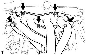
REMOVE NO. 1 EXHAUST MANIFOLD HEAT INSULATOR
-
Remove the 4 bolts and No. 1 exhaust manifold heat insulator.
-
-
REMOVE MANIFOLD STAY
-
Remove the bolt, nut and manifold stay.
-
-
REMOVE NO. 2 MANIFOLD STAY
-
Remove the bolt, nut and No. 2 manifold stay.
-
-
REMOVE EXHAUST MANIFOLD CONVERTER SUB-ASSEMBLY
-
Using a 12 mm deep socket wrench, remove the 5 nuts and exhaust manifold converter sub-assembly.
-
Remove the exhaust manifold to head gasket.
-
-
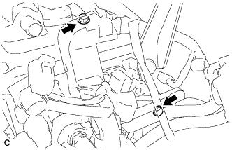
REMOVE WATER INLET
-
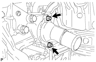
Remove the 2 nuts and water inlet from the cylinder block.
-
-
REMOVE THERMOSTAT
-
Remove the thermostat and gasket.
-
-
REMOVE NO. 4 WATER BY-PASS PIPE (for TMC Made Engine with Engine Oil Cooler)
-
for CVT:
-
Remove the nut, bolt and No. 4 water by-pass pipe.
-
-
-
REMOVE ENGINE OIL LEVEL DIPSTICK
-
Remove the engine oil level dipstick.
-
-
REMOVE ENGINE OIL LEVEL DIPSTICK GUIDE (for TMC Made Engine)
-
Remove the bolt and engine oil level dipstick guide.
-
Remove the O-ring from the engine oil level dipstick guide.
-
-
REMOVE ENGINE OIL LEVEL DIPSTICK GUIDE (except TMC Made Engine)
-
Remove the bolt and engine oil level dipstick guide.
-
Remove the O-ring from the engine oil level dipstick guide.
-
-
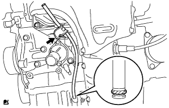
REMOVE NO. 1 WATER BY-PASS PIPE (for TMC Made Engine)
-
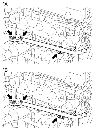
Text in Illustration *A for Automatic Transaxle
for CVT (w/o Air Cooled Transmission Oil Cooler)
*B for CVT (w/ Air Cooled Transmission Oil Cooler) Remove the bolt and 2 nuts, then remove the No. 1 water by-pass pipe.
-
Remove the gasket.
-
-
REMOVE NO. 1 WATER BY-PASS PIPE (except TMC Made Engine)
-
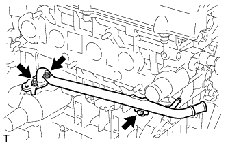
Remove the bolt and 2 nuts, then remove the No. 1 water by-pass pipe.
-
Remove the gasket.
-
-
REMOVE NO. 3 WATER BY-PASS PIPE (for CVT)
-
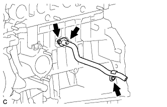
Remove the bolt and 2 nuts, then remove the No. 3 water by-pass pipe.
-
-
DISCONNECT NO. 3 WATER BY-PASS HOSE (for TMC Made Engine with Engine Oil Cooler)
-
Text in Illustration *1 No. 3 Water By-pass Hose *2 No. 4 Water By-pass Hose Disconnect the No. 3 water by-pass hose.
-
-
REMOVE NO. 4 WATER BY-PASS HOSE (for TMC Made Engine with Engine Oil Cooler)
-
Disconnect the No. 4 water by-pass hose.
-
-
REMOVE OIL COOLER PIPE (for TMC Made Engine with Engine Oil Cooler)
-
for Automatic Transaxle:
-
Remove the bolt, 2 nuts, oil cooler pipe and gasket.
-
-
-
REMOVE UNION BOLT (for TMC Made Engine with Engine Oil Cooler)
-
Remove the union bolt.
-
-
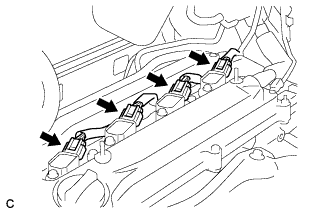
REMOVE IGNITION COIL ASSEMBLY
-
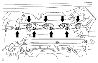
Disconnect the 4 ignition coil connectors.
-
Remove the 4 bolts and 4 ignition coils.
-
-
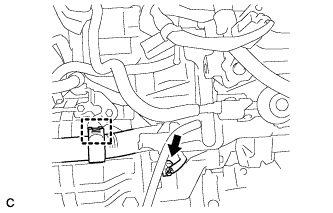
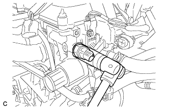
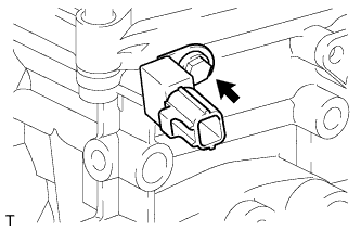
REMOVE KNOCK SENSOR
-
Disconnect the sensor connector.
-
Remove the nut and knock control sensor.
-
-
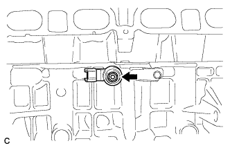
REMOVE OIL PRESSURE SWITCH
-
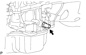
Disconnect the oil pressure switch connector.
-
Using a 24 mm deep socket wrench, remove the engine oil pressure switch assembly.
-
-
REMOVE ENGINE COOLANT TEMPERATURE SENSOR
-
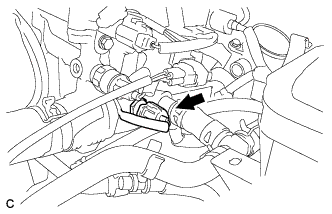
Disconnect the engine coolant temperature sensor connector.
-
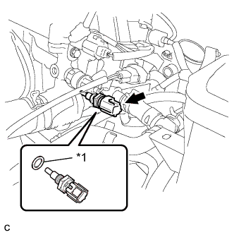
Text in Illustration *1 Gasket Remove the engine coolant temperature sensor and gasket.
-
-
REMOVE RADIO SETTING CONDENSER
-
Remove the bolt and radio setting condenser.
-
-
REMOVE STUD BOLT
-
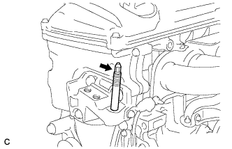
Using a socket wrench (8mm), remove the stud bolt from the engine mounting bracket RH.
-