СИСТЕМА SFI, Diagnostic DTC:P0031, P0032
| DTC Code | DTC Name |
|---|---|
| P0031 | Oxygen (A/F) Sensor Heater Control Circuit Low (Bank 1 Sensor 1) |
| P0032 | Oxygen (A/F) Sensor Heater Control Circuit High (Bank 1 Sensor 1) |
DESCRIPTION
Tech Tips
-
Although the DTC titles include oxygen sensor, these DTCs relate to the air fuel ratio sensor.
-
Sensor 1 refers to the sensor mounted in front of the three way catalytic converter and located near the engine assembly.
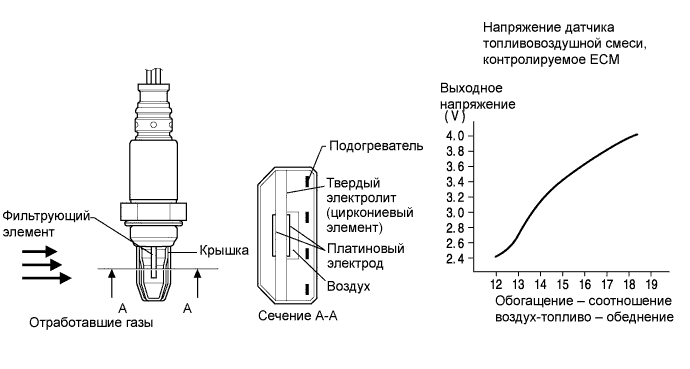
The air fuel ratio sensor generates voltage* that corresponds to the actual air fuel ratio. This sensor voltage is used to provide the ECM with feedback so that it can control the air fuel ratio. The ECM determines the deviation from the stoichiometric air fuel ratio level, and regulates the fuel injection time. If the air fuel ratio sensor malfunctions, the ECM is unable to control the air fuel ratio accurately.
The air fuel ratio sensor is the planar type and is integrated with a heater, which heats the solid electrolyte (zirconia element). This heater is controlled by the ECM. When the intake air volume is low (the exhaust gas temperature is low), a current flows into the heater to heat the sensor, in order to facilitate accurate oxygen concentration detection. In addition, the sensor and heater portions are narrower than the conventional type. The heat generated by the heater is conducted to the solid electrolyte through the alumina, therefore the sensor activation is accelerated.
In order to obtain a high purification rate of the carbon monoxide (CO), hydrocarbons (HC) and nitrogen oxide (NOx) components in the exhaust gas, a three way catalytic converter is used. For the most efficient use of the three way catalytic converter, the air fuel ratio must be precisely controlled so that it is always close to the stoichiometric level.
*: Value changes inside the ECM. Since the air fuel ratio sensor is the current output element, the current is converted to a voltage inside the ECM. Any measurements taken at the air fuel ratio sensor or ECM connectors will show a constant voltage.
Tech Tips
-
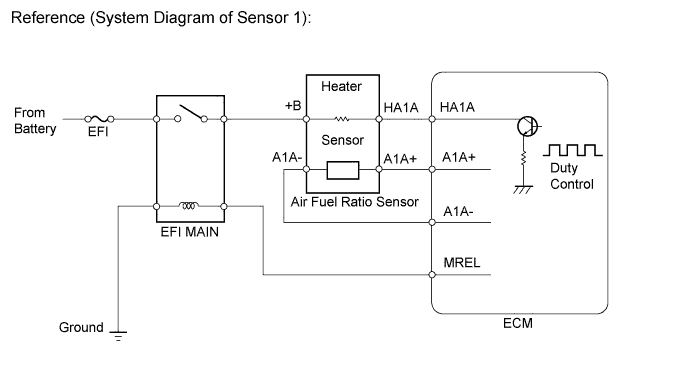
When any of these DTCs are set, the ECM enters fail-safe mode. The ECM turns off the air fuel ratio sensor heater in fail-safe mode. Fail-safe mode continues until the engine switch is turned off.
-
The ECM provides a pulse width modulated control circuit to adjust the current through the heater. The air fuel ratio sensor heater circuit uses a relay on the +B side of the circuit.
| DTC No. | DTC Detection Condition | Trouble Area |
|---|---|---|
| P0031 | Air fuel ratio sensor heater (sensor 1) current is less than 0.8 A (1 trip detection logic) |
|
| P0032 | Air fuel ratio sensor heater (sensor 1) current is more than 10 A (1 trip detection logic) |
|
| DTC No. | DTC Detection Condition | Trouble Area |
|---|---|---|
| P0031 | Air fuel ratio sensor heater (sensor 1) current is less than 0.8 A (1 trip detection logic) |
|
| P0032 | Air fuel ratio sensor heater (sensor 1) current is fail (1 trip detection logic) |
|
Tech Tips
-
Sensor 1 refers to the sensor closest to the engine assembly.
-
Sensor 2 refers to the sensor farthest away from the engine assembly.
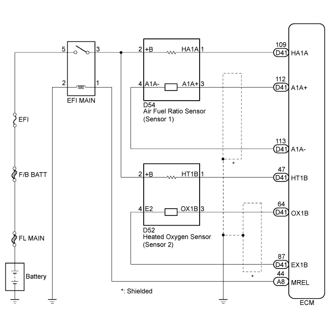
WIRING DIAGRAM
INSPECTION PROCEDURE
Note
Inspect the fuses for circuits related to this system before performing the following inspection procedure.
Tech Tips
Read freeze frame data using the intelligent tester. The ECM records vehicle and driving condition information as freeze frame data the moment a DTC is stored. When troubleshooting, freeze frame data can help determine if the vehicle was moving or stationary, if the engine was warmed up or not, if the air fuel ratio was lean or rich, and other data from the time the malfunction occurred.
PROCEDURE
-
INSPECT AIR FUEL RATIO SENSOR (HEATER RESISTANCE)
-
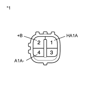
Text in Illustration *1 Component without harness connected
(Air Fuel Ratio Sensor)
Disconnect the air fuel ratio sensor connector.
-
Measure the resistance according to the value(s) in the table below.
Standard Resistance Tester Connection Condition Specified Condition 1 (HA1A) - 2 (+B) 20°C (68°F) 1.8 to 3.4 Ω 1 (HA1A) - 4 (A1A-) Always 10 kΩ or higher -
Reconnect the air fuel ratio sensor connector.
NG 
REPLACE AIR FUEL RATIO SENSOR Click here
OK 
-
-
CHECK TERMINAL VOLTAGE (+B OF AIR FUEL RATIO SENSOR)
-
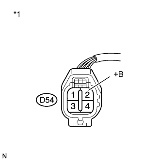
Text in Illustration *1 Front view of wire harness connector
(to Air Fuel Ratio Sensor)
Disconnect the air fuel ratio sensor connector.
-
Turn the engine switch on (IG).
-
Measure the voltage according to the value(s) in the table below.
Standard Voltage Tester Connection Switch Condition Specified Condition D54-2 (+B) - Body ground Engine switch on (IG) 11 to 14 V -
Reconnect the air fuel ratio sensor connector.
NG
REPAIR OR REPLACE HARNESS OR CONNECTOR (AIR FUEL RATIO SENSOR - EFI MAIN RELAY)
OK
-
-
CHECK HARNESS AND CONNECTOR (AIR FUEL RATIO SENSOR - ECM)
-
Disconnect the air fuel ratio sensor connector.
-
Disconnect the ECM connector.
-
Measure the resistance according to the value(s) in the table below.
Standard Resistance (Check for Open) Tester Connection Condition Specified Condition D54-1 (HA1A) - D41-109 (HA1A) Always Below 1 Ω Standard Resistance (Check for Short) Tester Connection Condition Specified Condition D54-1 (HA1A) or D41-109 (HA1A) - Body ground Always 10 kΩ or higher -
Reconnect the air fuel ratio sensor connector.
-
Reconnect the ECM connector.
NG
REPAIR OR REPLACE HARNESS OR CONNECTOR (AIR FUEL RATIO SENSOR - ECM)
OK
-
-
CHECK WHETHER DTC OUTPUT RECURS (DTC P0031 OR P0032)
-
Connect the intelligent tester to the DLC3.
-
Turn the engine switch on (IG).
-
Turn the tester on.
-
Clear the DTCs Click here.
-
Start the engine and allow the engine to idle for 1 minute or more.
-
Enter the following menus: Powertrain / Engine and ECT / DTC.
-
Read the DTCs.
Result Result Proceed to DTC is not output A DTC P0031 or P0032 is output B
B
REPLACE ECM Click here
A 
CHECK FOR INTERMITTENT PROBLEMS Click here
-