CAN COMMUNICATION SYSTEM TERMINALS OF ECU

Note
-
Turn the ignition switch off before measuring the resistances of the CAN main wire and the CAN branch wire.
-
After the ignition switch is turned off, check that the light reminder warning system is not in operation.
-
Before measuring the resistance, leave the vehicle as is for at least 1 minute and do not operate the ignition switch, any other switches or the doors. If doors need to be opened in order to check connectors, open the doors and leave them open.
Tech Tips
Operating the ignition switch, any switches or any doors triggers related ECU and sensor communication with the CAN, which causes resistance variation.
-
JUNCTION CONNECTOR
-
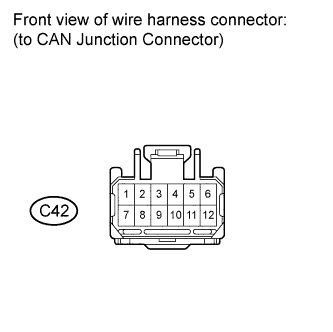
CAN Junction Connector
Wiring Color D-CAN Junction Connector Terminal No. (Symbol) Wiring Color Steering sensor (CAN-H) C42-10 (CANH) B Steering sensor (CAN-L) C42-4 (CANL) W DLC 3 (CAN-H) C42-7 (CANH) B DLC 3 (CAN-L) C42-1 (CANL) W -

CAN Junction Connector
Wiring Color P-CAN Junction Connector Terminal No. (Symbol) Wiring Color ABS and traction actuator (skid control ECU) (CAN-H) A38-9 (CANH) B ABS and traction actuator (skid control ECU) (CAN-L) A38-3 (CANL) W Yaw rate sensor (CAN-H) A38-7 (CANH) B Yaw rate sensor (CAN-L) A38-1 (CANL) W ECM*1 (CAN-H) A38-8 (CANH) B ECM*1 (CAN-L) A38-2 (CANL) W ECM*2 (CAN-H) A38-8 (CAN+) B ECM*2 (CAN-L) A38-2 (CAN-) W Transmission control ECU (CAN-H) A38-10 (CANH) B Transmission control ECU (CAN-L) A38-4 (CANL) W *1: 2WZ-TV
*2: 1KR-FE
-
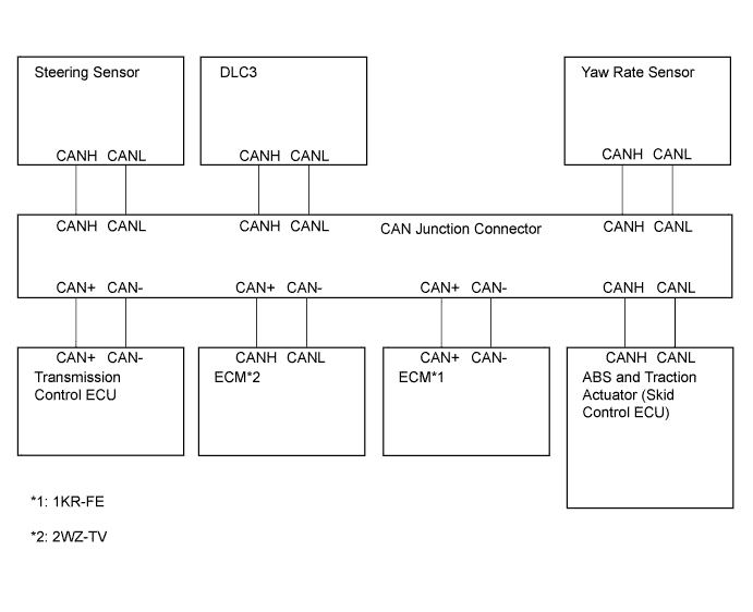
Wiring diagram for identifying CAN junction connectors
-
-
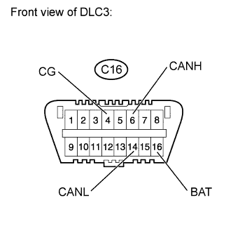
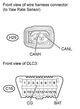
DLC3
Tech Tips
For 2WZ-TV only.
-
Turn the ignition switch off.
-
Measure the resistance according to the value(s) in the table below.
Standard Resistance Terminal No. (Symbol) Wiring Color Switch Condition Specified Condition C16-6 (CANH) - C16-14 (CANL) B - W Ignition switch off*
54 to 69 Ω C16-6 (CANH) - C16-4 (CG) B - W-B Ignition switch off*
200 Ω or higher C16-14 (CANL) - C16-4 (CG) W - W-B Ignition switch off*
200 Ω or higher C16-6 (CANH) - C16-16 (BAT) B - BE Ignition switch off*
6 kΩ or higher C16-14 (CANL) - C16-16 (BAT) W - BE Ignition switch off*
6 kΩ or higher Note
*:Before measuring the resistance, leave the vehicle as is for at least 1 minute and do not operate the ignition switch, any other switches or the doors.
-
-
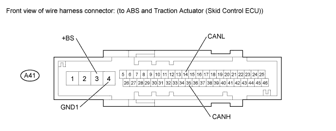
ABS AND TRACTION ACTUATOR (SKID CONTROL ECU)
-
Turn the ignition switch off.
-
Disconnect the A41 ABS and traction actuator (skid control ECU) connector.
-
Measure the resistance according to the value(s) in the table below.
Standard Resistance Terminal No. (Symbol) Wiring Color Switch Condition Specified Condition A41-35 (CANH) - A41-14 (CANL) B - W Ignition switch off 54 to 69 Ω A41-35 (CANH) - A41-4 (GND1) B - BR Ignition switch off 200 Ω or higher A41-14 (CANL) - A41-4 (GND1) W - BR Ignition switch off 200 Ω or higher A41-35 (CANH) - A41-3 (+BS) B - R Ignition switch off 6 kΩ or higher A41-14 (CANL) - A41-3 (+BS) W - R Ignition switch off 6 kΩ or higher
-
-
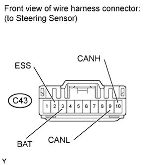
STEERING SENSOR
-
Turn the ignition switch off.
-
Disconnect the C43 steering sensor connector.
-
Measure the resistance according to the value(s) in the table below.
Standard Resistance Terminal No. (Symbol) Wiring Color Switch Condition Specified Condition C43-10 (CANH) - C43-9 (CANL) B - W Ignition switch off 108 to 132 Ω C43-10 (CANH) - C43-2 (ESS) B - W-B Ignition switch off 200 Ω or higher C43-9 (CANL) - C43-2 (ESS) W - W-B Ignition switch off 200 Ω or higher C43-10 (CANH) - C43-3 (BAT) B - LG Ignition switch off 6 kΩ or higher C43-9 (CANL) - C43-3 (BAT) W - LG Ignition switch off 6 kΩ or higher
-
-
YAW RATE SENSOR
-
Turn the ignition switch off.
-
Disconnect the H25 yaw rate sensor connector.
-
Measure the resistance according to the value(s) in the table below.
Standard Resistance Terminal No. (Symbol) Wiring Color Switch Condition Specified Condition H25-3 (CANH) - H25-1 (CANL) B - W Ignition switch off 54 to 69 Ω H25-3 (CANH) - C16-4 (CG) B - W-B Ignition switch off 200 Ω or higher H25-1 (CANL) - C16-4 (CG) W - W-B Ignition switch off 200 Ω or higher H25-3 (CANH) - C16-16 (BAT) B - BE Ignition switch off 6 kΩ or higher H25-1 (CANL) - C16-16 (BAT) W - BE Ignition switch off 6 kΩ or higher
-
-
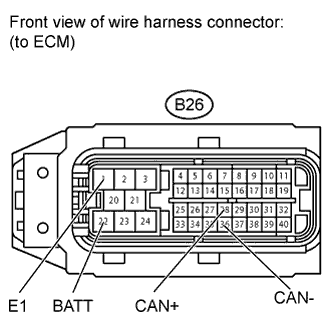
ECM (1KR-FE Engine)
-
Turn the ignition switch off.
-
Disconnect the B26 ECM connector.
-
Measure the resistance according to the value(s) in the table below.
Standard Resistance Terminal No. (Symbol) Wiring Color Switch Condition Specified Condition B26-28 (CAN+) - B26-36 (CAN-) B - W Ignition switch off 108 to 132 Ω B26-28 (CAN+) - B26-1 (E1) B - W-B Ignition switch off 200 Ω or higher B26-36 (CAN-) - B26-1 (E1) W - W-B Ignition switch off 200 Ω or higher B26-28 (CAN+) - B26-22 (BATT) B - LG Ignition switch off 6 kΩ or higher B26-36 (CAN-) - B26-22 (BATT) W - LG Ignition switch off 6 kΩ or higher
-
-
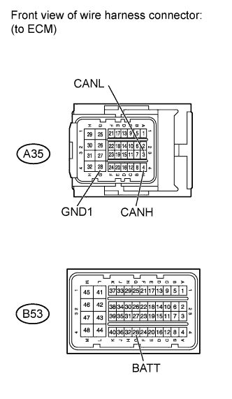
ECM (for LHD of 2WZ-TV Engine)
-
Turn the ignition switch off.
-
Disconnect the A35 and B53 ECM connectors.
-
Measure the resistance according to the value(s) in the table below.
Standard Resistance Terminal No. (Symbol) Wiring Color Switch Condition Specified Condition A35-4 (CANH) - A35-3 (CANL) B - W Ignition switch off 108 to 132 Ω A35-4 (CANH) - A35-28 (GND1) B - W-B Ignition switch off 200 Ω or higher A35-3 (CANL) - A35-28 (GND1) W - W-B Ignition switch off 200 Ω or higher A35-4 (CANH) - B53-28 (BATT) B - 1226A Ignition switch off 6 kΩ or higher A35-3 (CANL) - B53-28 (BATT) W - 1226A Ignition switch off 6 kΩ or higher
-
-
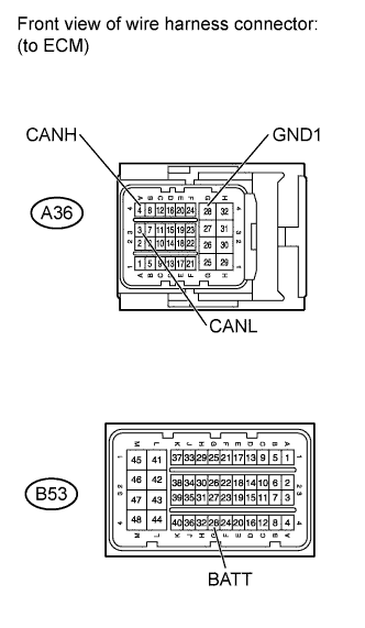
ECM (for RHD of 2WZ-TV Engine)
-
Turn the ignition switch off.
-
Disconnect the A36 and B53 ECM connectors.
-
Measure the resistance according to the value(s) in the table below.
Standard Resistance Terminal No. (Symbol) Wiring Color Switch Condition Specified Condition A36-4 (CANH) - A36-3 (CANL) B - W Ignition switch off 108 to 132 Ω A36-4 (CANH) - A36-28 (GND1) B - W-B Ignition switch off 200 Ω or higher A36-3 (CANL) - A36-28 (GND1) W - W-B Ignition switch off 200 Ω or higher A36-4 (CANH) - B53-28 (BATT) B - 1226A Ignition switch off 6 kΩ or higher A36-3 (CANL) - B53-28 (BATT) W - 1226A Ignition switch off 6 kΩ or higher
-
-
TRANSMISSION CONTROL ECU
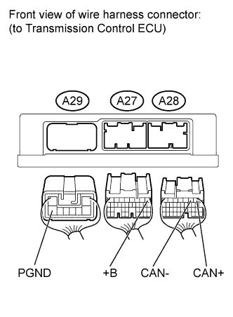
Tech Tips
For vehicle with multi-mode transaxle system only.
-
Turn the ignition switch off.
-
Disconnect the A27, A28 and A29 transmission control ECU connectors.
-
Measure the resistance according to the value(s) in the table below.
Standard Resistance Terminal No. (Symbol) Wiring Color Switch Condition Specified Condition A28-1 (CAN+) - A28-2 (CAN-) B - W Ignition switch off 54 to 69 Ω A28-1 (CAN+) - A29-8 (PGND) B - W-B Ignition switch off 200 Ω or higher A28-2 (CAN-) - A29-8 (PGND) W - W-B Ignition switch off 200 Ω or higher A28-1 (CAN+) - A27-1 (+B) B - B Ignition switch off 6 kΩ or higher A28-2 (CAN-) - A27-1 (+B) W - B Ignition switch off 6 kΩ or higher
-