CAN COMMUNICATION SYSTEM PRECAUTION

-
PRECAUTION
-
Turn the ignition switch to OFF before measuring the resistances of the CAN main wire and the CAN branch wire.
-
After the ignition switch is turned to OFF, check that the light reminder warning system is not in operation.
-
Before measuring the resistance, leave the vehicle as is for at least 1 minute and do not operate the ignition switch, any other switches or the doors. If doors need to be opened in order to check connectors, open the doors and leave them open.
Tech Tips
Operating the ignition switch, any switches or any doors triggers related ECU and sensor communication with the CAN, which causes resistance variation.
-
-
SRS AIRBAG SYSTEM HANDLING PRECAUTIONS
-
This vehicle is equipped with an SRS (Supplemental Restraint System) such as the driver airbag and front passenger airbag. Failure to carry out service operations in the correct sequence could cause unexpected SRS deployment during servicing and may lead to a serious accident. Before servicing (including removal or installation of parts, inspection or replacement), be sure to read the precautionary notice for the Supplemental Restraint System Click here.
-
-
BUS LINE REPAIR
-
After repairing the bus line with solder, wrap the repaired part with vinyl tape Click here.
Note
-
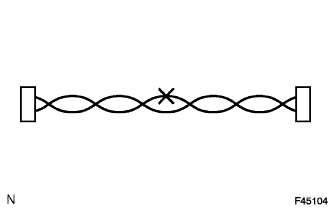
The CANL bus line and CANH bus line must be installed together.
-
When installing, twist them together.
-
CAN bus lines are likely to be influenced by noise if the bus lines are not twist together.
-
The difference in length between the CANL bus line and CANH bus line should be less than 100 mm (3.937 in.).
-
Leave approximately 80 mm (3.150 in.) loose in the twisted wires around the connectors.
-
-
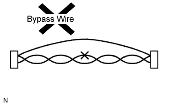
Do not use bypass wiring between the connectors.
Note
The benefits of the twisted wire harness will be lost if bypass wiring is used.
-
-
CONNECTOR HANDLING
-
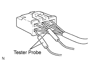
When inserting tester probes into a connector, insert them from the rear of the connector.
-
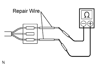
Use a repair wire to check the connector if it is impossible to check resistance from the rear of the connector.
-