CAN COMMUNICATION SYSTEM CAN Main Wire for Disconnection
DESCRIPTION
There may be an open circuit in the main wire and/or the yaw rate sensor branch wire when the resistance between terminals 10 (CANH) and 9 (CANL) of the yaw rate sensor connector is 69Ω or higher.
| Symptom | Trouble Area |
|---|---|
| Resistance between terminals 10 (CANH) and 9 (CANL) of yaw rate sensor connector 69Ω or higher. |
|
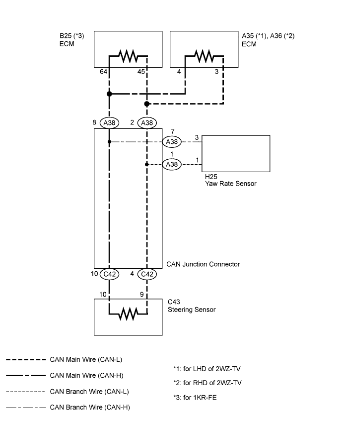
WIRING DIAGRAM
INSPECTION PROCEDURE
Note
-
Turn the ignition switch to off before measuring the resistances of the CAN main wire and the CAN branch wire.
-
After the ignition switch is turned to OFF, check that the light reminder warning system is not in operation.
-
Before measuring the resistance, leave the vehicle as is for at least 1 minute and do not operate the ignition switch, any other switches or the doors. If doors need to be opened in order to check connectors, open the doors and leave them open.
Tech Tips
Operating the ignition switch, any switches or any doors triggers related ECU and sensor communication with the CAN, which causes resistance variation.
PROCEDURE
-
CHECK CAN BUS WIRE (YAW RATE SENSOR - CAN J/C)
-
Turn the ignition switch to OFF.
-
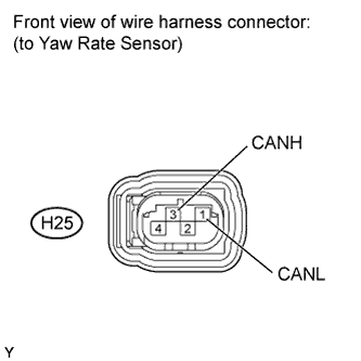
Disconnect the H25 yaw rate sensor connector.
-
Measure the resistance according to the value in the table below.
Standard resistance Tester Connection Switch Condition Specified Condition H25-3 (CANH) - H25-1 (CANL) Ignition switch OFF 108 to 132 Ω Note
When the measured value is 132 Ω or higher and a CAN communication system diagnostic trouble code is output, there may be a fault besides disconnection of the yaw rate sensor branch wire. For that reason, troubleshooting should be performed again from "HOW TO PROCEED WITH TROUBLESHOOTING" Click here after repairing the trouble area.
NG 
REPAIR OR REPLACE CAN BRANCH WIRE CONNECTED TO YAW RATE SENSOR (CAN-H, CAN-L)
OK 
-
-
CHECK CAN MAIN WIRE OR CONNECTOR (ECM SIDE)
-
Turn the ignition switch to OFF.
-
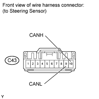
Disconnect the C43 steering sensor connector.
-
Measure the resistance according to the value in the table below.
Standard resistance Tester Connection Switch Condition Specified Condition C43-10 (CANH) - C43-9 (CANL) Ignition switch OFF 108 to 132 Ω
OK
REPLACE STEERING SENSOR
NG
-
-
CONNECT CONNECTOR
-
Reconnect the steering sensor connector.
NEXT
-
-
CHECK CAN MAIN WIRE OR CONNECTOR (STEERING SENSOR SIDE)
-
Turn the ignition switch to OFF.
-
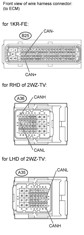
Disconnect the B25, A35 or A36 ECM connector.
-
Measure the resistance according to the value in the table below.
Standard resistance for 1KR-FE: Tester Connection Switch Condition Specified Condition B25-64 (CAN+) - B25-45 (CAN-) Ignition switch OFF 108 to 132 Ω for LHD of 2WZ-TV: Tester Connection Switch Condition Specified Condition A35-4 (CANH) - A35-3 (CANL) Ignition switch OFF 108 to 132 Ω for RHD of 2WZ-TV: Tester Connection Switch Condition Specified Condition A36-4 (CANH) - A36-3 (CANL) Ignition switch OFF 108 to 132 Ω
OK
REPLACE ECM
NG
-
-
CONNECT CONNECTOR
-
Reconnect the ECM connector.
NEXT
-
-
CHECK CAN MAIN WIRE OR CONNECTOR (ECM - CAN J/C)
-
Turn the ignition switch to OFF.
-
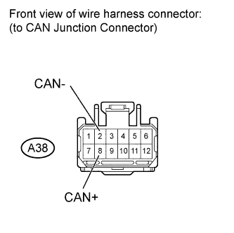
Disconnect the A38 CAN junction connector.
-
Measure the resistance according to the value(s) in the table below.
Standard resistance Tester Connection Switch Condition Specified Condition A38-8 (CAN+) - A38-2 (CAN-) Ignition switch OFF 103 to 132 Ω
NG
REPAIR OR REPLACE CAN MAIN WIRE OR CONNECTOR (ECM - CAN J/C)
OK
-
-
CHECK CAN MAIN WIRE OR CONNECTOR (STEERING SENSOR - CAN J/C)
-
Turn the ignition switch to OFF.
-
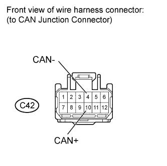
Disconnect the C42 CAN junction connector.
-
Measure the resistance according to the value(s) in the table below.
Standard resistance Tester Connection Switch Condition Specified Condition C42-10 (CAN+) - C42-4 (CAN-) Ignition switch OFF 103 to 132 Ω
NG
REPAIR OR REPLACE CAN MAIN WIRE OR CONNECTOR (STEERING SENSOR - CAN J/C)
OK 
REPLACE CAN J/C
-