FRONT BUMPER INSTALLATION

-
INSTALL FRONT BUMPER HOLE COVER RH
-
Engage the 3 claws and install the front bumper hole cover.
-
-
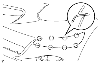
INSTALL FRONT BUMPER SIDE MOULDING LH
-
Engage the 8 claws and install the front bumper side moulding.
-
-
INSTALL FRONT BUMPER SIDE MOULDING RH
Tech Tips
Use the same procedure as for the LH side.
-
INSTALL FOG LIGHT COVER LH
-
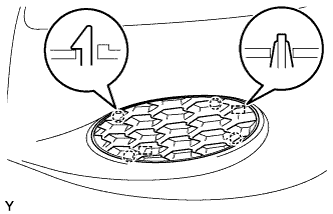
Engage the 4 claws and 2 guides and install the fog light cover.
-
-
INSTALL FOG LIGHT COVER RH
Tech Tips
Use the same procedure as for the LH side.
-
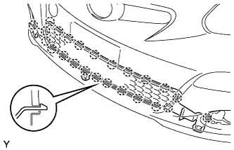
INSTALL RADIATOR GRILLE LOWER
-
Engage the 24 claws and install the radiator grille lower.
-
-
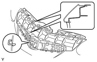
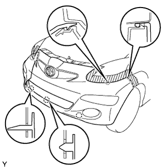
INSTALL RADIATOR GRILLE
-
Engage the 21 claws and install the radiator grille.
-
-
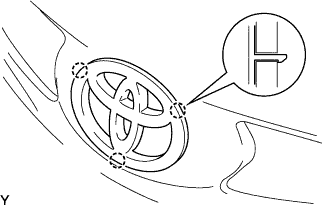
INSTALL RADIATOR GRILLE EMBLEM
-
Engage the 3 claws and install the radiator grille emblem.
-
-
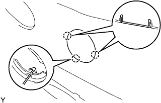
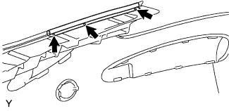
INSTALL HOOD TO FRONT END PANEL SEAL
-
Engage the 3 clips and install the 2 hood to front end panel seals.
-
-
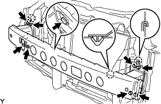
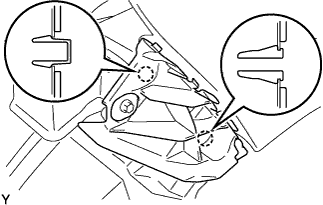
INSTALL FRONT BUMPER REINFORCEMENT SUB-ASSEMBLY
-
Hook the 2 hooks of the front bumper reinforcement onto the body.
-
Install the front bumper reinforcement with the 8 bolts.
- Torque:
- 64 N*m { 655 kgf*cm, 47 ft.*lbf }
-
Engage the claw.
-
Install the clip.
-
-
INSTALL FRONT BUMPER SIDE RETAINER LH
-
Engage the 2 claws and install the front bumper side retainer.
-
-
INSTALL FRONT BUMPER SIDE RETAINER RH
Tech Tips
Use the same procedure as for the LH side.
-
INSTALL HEADLIGHT UNIT LH
-
Connect the 4 connectors.
-
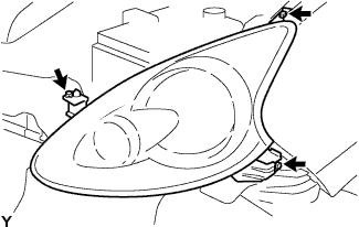
Install the headlight unit LH with the 3 screws.
-
-
INSTALL HEADLIGHT UNIT RH
Tech Tips
Use the same procedure as for the LH side.
-
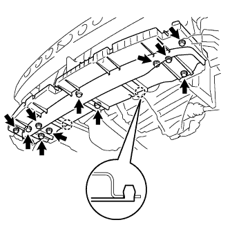
INSTALL ENGINE UNDER COVER AIR GUIDE
-
Engage the 2 claws and install the engine under cover air guide.
-
Tighten the 9 bolts and 2 screws.
-
-
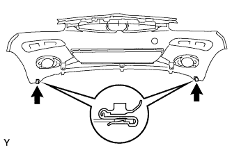
INSTALL FRONT BUMPER COVER
-
Install the 2 clips.
-
Engage the 13 claws and install the front bumper cover.
-
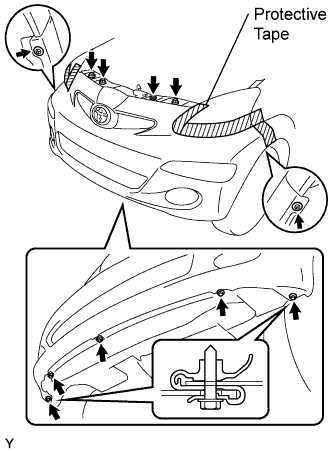
Tighten the 3 bolts and 5 screws.
-
Install the 3 clips.
-
Remove the protective tape.
-
-
PREPARE VEHICLE FOR HEADLIGHT AIM ADJUSTMENT
-
Prepare the vehicle:
-
Ensure that there is no damage or deformation of the body around the headlights.
-
Fill the fuel tank.
-
Make sure that the oil is filled to the specified level.
-
Make sure that the coolant is filled to the specified level.
-
Inflate the tires to the appropriate pressure.
-
Place the spare tire, tools, and jack in their original positions.
-
Unlock the trunk.
-
Sit a person of average weight (75 kg, 165 lb) in the drivers seat.
-
-
-
PREPARE FOR HEADLIGHT AIMING
-
Prepare the vehicle in accordance with the following:
-
Place the vehicle in a location that is dark enough to clearly observe the cutoff line. The cutoff line is a distinct line, below which light from the headlights can be observed and above which it cannot.
-
Place the vehicle at a 90° angle to the wall.
-
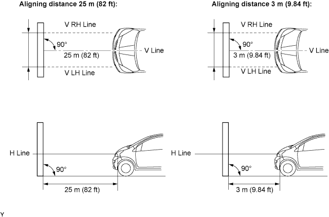
Keep a 25 m (82 ft) distance between the center of the headlight bulb and the wall.
-
Place the vehicle on a level surface.
-
Bounce the vehicle up and down to settle the suspension.
Note
A distance of 25 m (82 ft) between the vehicle (the center of the headlight bulb) and the wall is necessary for proper aim adjustment. If unable to secure a distance of 25 m (82 ft), set a distance of exactly 3 m (9.84 ft) to check and adjust the headlight aim. (Since the target zone changes depending on the distance, follow the instructions shown in the illustration.)
-
-
Prepare a piece of thick white paper (approximately 2 m (6.6 ft) high x 4 m (13.1 ft) wide) to use as a screen.
-
Draw a vertical line down the center of the screen (V line).
-
Set the screen, as shown in the illustration.
Tech Tips
-
Stand the screen perpendicular to the ground.
-
Align the V line on the screen with the center of the vehicle.
-
-
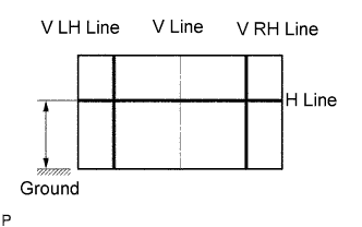
Draw base lines (H line, V LH and V RH lines) on the screen, as shown in the illustration.
Tech Tips
-
The base lines differ for low-beam inspection and high-beam inspection.
-
Mark the headlight bulb center marks on the screen. If the center mark cannot be observed on the headlight, use the center of the headlight bulb.
-
H Line (Headlight height):
Draw a horizontal line across the screen so that it passes through the center marks. The H line should be at the same height as the headlight bulb center marks of the low-beam headlights.
-
V LH Line and V RH Line (Center mark position of left-hand (LH) and right-hand (RH) headlights):
Draw two vertical lines so that they intersect the H line at each center mark (aligned with the center of the low-beam headlight bulbs).
-
-
-
INSPECT HEADLIGHT AIMING
-
Cover the headlight on the opposite side or disconnect its connector, to prevent light from the headlight not being inspected from affecting the headlight aiming inspection.
Note
Do not keep the headlight covered for more than 3 minutes. The headlight lens is made of synthetic resin, and may easily melt or be damaged due to heat.
-
Start the engine.
Note
Engine rpm must be 1,500 or more.
-
Set the headlight leveling switch to 0 (zero).
-
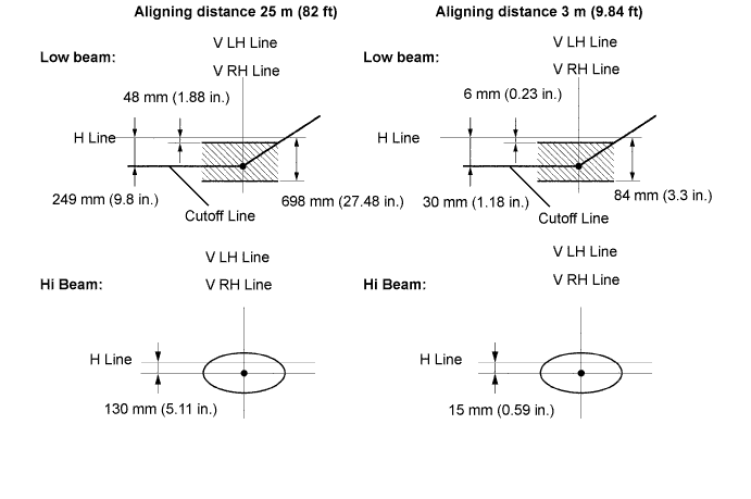
Turn on the headlight and make sure that the cutoff line falls within the specified area, as shown in the illustration.
Tech Tips
-
Alignment distance is 25 m (82 ft):
The cutoff line is 48 mm (1.88 in.) to 698 mm (27.48 in.) below the H line with low-beam (ECE Regulation No. 48).
-
Alignment distance is 3 m (9.84 ft):
The cutoff line is 6 mm (0.23 in.) to 84 mm (3.3 in.) below the H line with low-beam (ECE Regulation No. 48).
-
Alignment distance is 25 m (82 ft):
The cutoff line is 249mm (9.8 in.) below the H line with low-beam.
-
Alignment distance is 3 m (9.84 ft):
The cutoff line is 30 mm (1.18 in.) below the H line with low-beam.
-
Since the low-beam light and the high-beam light are a unit, if the aiming on one is correct, the other should also be correct. However, check both beams just to make sure.
-
-
-
ADJUST HEADLIGHT AIMING
-
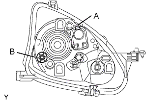
Adjust the aiming vertically:
Adjust the headlight aim into the specified range by turning aiming screw A with a screwdriver.
Note
The final turn of the aiming screw should be made in the clockwise direction. If the screw is tightened excessively, loosen it and then retighten it, so that the final turn of the screw is in the clockwise direction.
-
Perform low-beam aim adjustment.
Tech Tips
The headlight aim moves down when the aiming screw is turned clockwise, and moves up when the aiming screw is turned counterclockwise.
-
Adjust the aim horizontally:
Adjust the headlight aim into the specified range by turning aiming screw B with a screwdriver.
Note
The final turn of the aiming screw should be made in the clockwise direction. If the screw is tightened excessively, loosen it and then retighten it, so that the final turn of the screw is in the clockwise direction.
-