FRONT DOOR (w/ Power Window) DISASSEMBLY

Tech Tips
-
Use the same procedure for both the RH and LH sides.
-
The procedure described below is for the LH side.
-
PRECAUTION
Note
After turning the ignition switch off, waiting time may be required before disconnecting the cable from the battery terminal. Therefore, make sure to read the disconnecting the cable from the battery terminal notice before proceeding with work Click here
-
DISCONNECT CABLE FROM NEGATIVE BATTERY TERMINAL
CAUTION:
Wait for at least 90 seconds after disconnecting the cable from the negative (-) battery terminal to disable the SRS system.
-
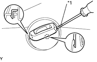
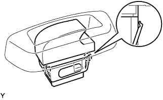
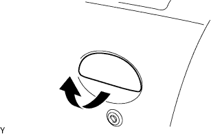
REMOVE DOOR ASSIST GRIP COVER
-
Text in Illustration *1 Protective Tape Using a screwdriver with its tip wrapped in protective tape, disengage the 2 claws and remove the door assist grip cover.
-
-
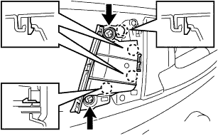
REMOVE ASSIST GRIP ASSEMBLY
-
Remove the 2 screws.
-
Disengage the 4 claws and remove the assist grip assembly.
-
-
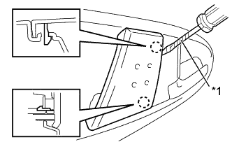
REMOVE FRONT ARMREST UPPER BASE PANEL
-
Text in Illustration *1 Protective Tape Using a screwdriver with its tip wrapped in protective tape, disengage the 3 claws and remove the front armrest upper base panel.
-
Disconnect the connector and remove the front armrest upper base panel.
-
-
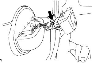
REMOVE POWER WINDOW REGULATOR SWITCH ASSEMBLY
-
Disengage the 2 claws and remove the power window regulator switch assembly.
-
-
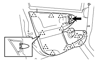
REMOVE FRONT DOOR TRIM BOARD SUB-ASSEMBLY (for 5 Door)
-
Remove the screw.
-
Disengage the 13 clips and remove the front door trim board sub-assembly.
-
Disconnect the connector.
CAUTION:
When removing the front door trim board sub-assembly, take care not to damage the rear No. 3 speaker assembly wire harness.
-
-
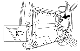
REMOVE FRONT DOOR TRIM BOARD SUB-ASSEMBLY (for 3 Door)
-
Remove the screw.
-
Disengage the 15 clips and remove the front door trim board sub-assembly.
-
Disconnect the connector.
CAUTION:
When removing the front door trim board sub-assembly, take care not to damage the rear No. 3 speaker assembly wire harness.
-
-
REMOVE REAR NO. 3 SPEAKER ASSEMBLY
-
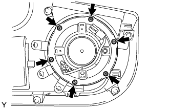
Remove the 6 screws and the rear No. 3 speaker.
-
-
REMOVE FRONT DOOR SERVICE HOLE COVER
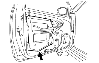
-
Remove the front door service hole cover.
Tech Tips
Remove any tape remaining on the door side.
-
-
REMOVE FRONT DOOR NO. 2 SERVICE HOLE COVER
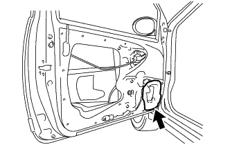
-
Remove the front door No. 2 service hole cover.
Tech Tips
Remove any tape remaining on the door side.
-
-
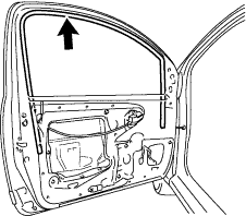
REMOVE FRONT DOOR FRONT LOWER FRAME UPPER COVER
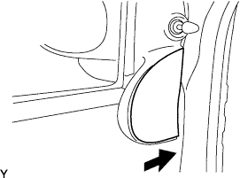
-
Remove the front door front lower frame upper cover by sliding it in the direction indicated by the arrow in the illustration.
-
-
REMOVE FRONT DOOR LOWER FRAME BRACKET GARNISH
-
Remove the 2 screws.
-
Disengage the 2 clips and remove the front door lower frame bracket garnish.
-
-
REMOVE OUTER REAR VIEW MIRROR ASSEMBLY
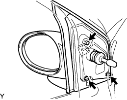
-
Remove the 3 screws and outer rear view mirror assembly LH.
-
-
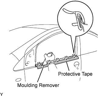
REMOVE FRONT DOOR GLASS OUTER WEATHERSTRIP ASSEMBLY (for 5 Door)
-
Apply protective tape to the outer circumference of the front door belt moulding, as shown in the illustration.
-
Using a moulding remover, disengage the 5 claws and remove the front door belt moulding.
-
-
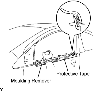
REMOVE FRONT DOOR GLASS OUTER WEATHERSTRIP ASSEMBLY (for 3 Door)
-
Apply protective tape to the outer circumference of the front door belt moulding, as shown in the illustration.
-
Using a moulding remover, disengage the 6 claws and remove the front door belt moulding.
-
-
REMOVE FRONT DOOR GLASS INNER WEATHERSTRIP ASSEMBLY
-
REMOVE FRONT DOOR GLASS RUN
-
Remove the front door glass run.
-
-
REMOVE FRONT DOOR GLASS SUB-ASSEMBLY
-
Connect the power window regulator switch.
-
Connect cable to the negative (-) battery terminal.
-
Remove the hole plug.
-
Move the door glass until the 2 bolts can be seen through the service holes.
-
Disconnect the cable front the negative (-) battery terminal.
-
Remove the 2 bolts and front door glass sub-assembly.
Note
Do not allow the front door glass sub-assembly to fall or be damaged when removing the screw.
-
Disconnect the power window regulator switch.
-
-
REMOVE FRONT DOOR WINDOW REGULATOR SUB-ASSEMBLY
-
Disconnect the connector.
-
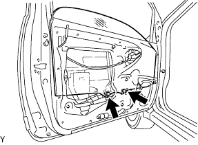
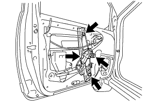
Remove the 3 nuts and front door window regulator sub-assembly.
Note
Do not drop the front door window regulator sub-assembly when removing the nuts.
Tech Tips
Remove the front door window regulator sub-assembly through the service hole.
-
-
REMOVE FRONT DOOR FRONT LOWER FRAME SUB-ASSEMBLY
-
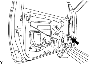
Remove the bolt and front door front lower frame sub-assembly.
-
-
REMOVE FRONT DOOR REAR LOWER FRAME SUB-ASSEMBLY
-
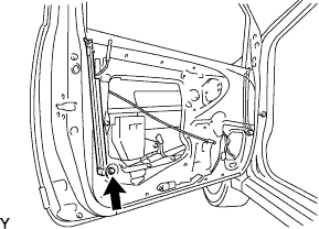
Remove the bolt and front door rear lower frame sub-assembly.
-
-
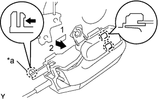
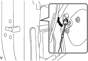
REMOVE FRONT DOOR INSIDE HANDLE SUB-ASSEMBLY
-
Disengage claw A.
Text in Illustration *a Claw A -
Move the front door inside handle sub-assembly in the direction indicated by the arrow mark in the illustration. This will release the 2 claws and allow the removal of the front door inside handle sub-assembly.
-
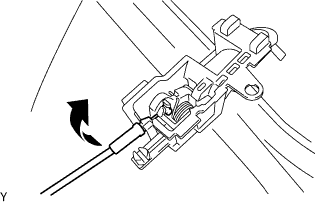
Disconnect the cable from the front door inside handle sub-assembly by pulling it in the direction indicated by the arrow in the illustration.
-
-
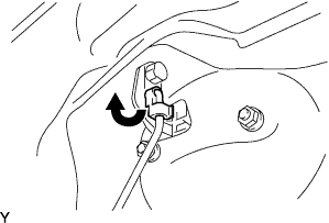
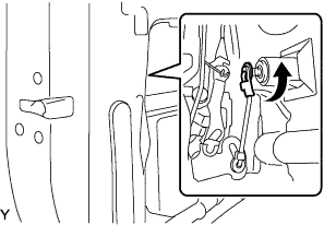
REMOVE FRONT DOOR OUTSIDE HANDLE ASSEMBLY
-
Separate the round bar by turning the fastener in the direction indicated by the arrow in the illustration.
-
Remove the round bar from the front door outside handle assembly.
-
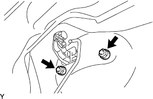
Remove the 2 nuts.
-
Remove the front door outside handle assembly in the direction shown in the illustration.
-
-
REMOVE FRONT DOOR LOCK ASSEMBLY
-
Disconnect the front door lock open rod, as shown in the illustration.
-
Disconnect the front outside locking link, as shown in the illustration.
-
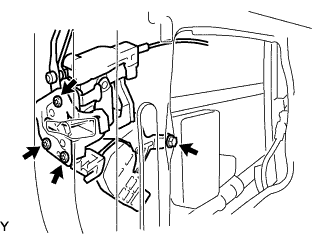
Remove the bolt.
-
Using T30 "TORX" socket wrench, remove the 3 screws and front door lock assembly.
-
-
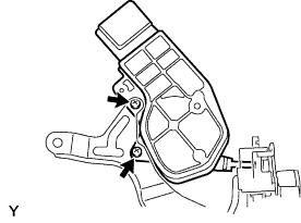
REMOVE FRONT DOOR LOCK ACTUATOR ASSEMBLY
-
Remove the 2 screws and front door lock actuator assembly.
-
-
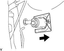
REMOVE DOOR LOCK CYLINDER AND KEY SET
-
Remove the retainer in the direction indicated by the arrow in the illustration.
-
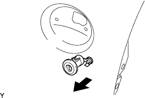
Remove the door lock cylinder and key set.
-
-
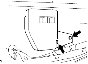
REMOVE FRONT DOOR NO. 2 STIFFENER CUSHION
-
Remove the 2 bolts and front door No. 2 stiffener cushion.
-
-
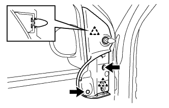
REMOVE SIDE AIRBAG SENSOR ASSEMBLY (for 3 Door)
-
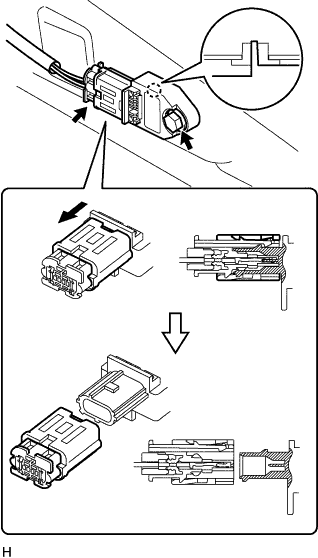
Disconnect the airbag sensor connector, as shown in the illustration.
-
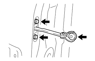
Remove the bolt, hook and side airbag sensor.
-
-
REMOVE FRONT DOOR CHECK ASSEMBLY
-
Remove the 2 bolts.
-
Using a T40 "TORX" socket wrench, remove the screw and front door check assembly.
Tech Tips
Remove the front door check assembly through the service hole.
-