LOWER INSTRUMENT PANEL INSTALLATION

-
INSTALL INSTRUMENT CLUSTER LOWER FINISH PANEL GARNISH
-
Engage the 3 claws and install the instrument cluster lower finish panel garnish.
-
Install the screw <B>.
-
-
INSTALL NO. 1 STEREO JACK ADAPTER ASSEMBLY
-
Connect the 2 connectors.
-
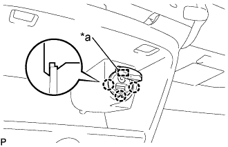
Text in Illustration *a Protrusion Align the protrusion of the stereo jack adapter with the cutout of the instrument cluster lower finish panel garnish.
-
Engage the 3 claws and install the stereo jack adapter.
-
-
INSTALL INSTRUMENT PANEL ASSEMBLY LOWER
-
Engage the 2 claws.
-
Install the 8 screws <B>.
-
-
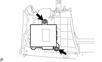
INSTALL POWER STEERING ECU ASSEMBLY
-
Install the power steering ECU assembly to the instrument panel assembly lower with the 2 bolts.
- Torque:
- 1.7 N*m { 17 kgf*cm, 15 in.*lbf }
-
-
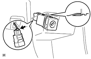
INSTALL AIRBAG CUT OFF SWITCH CYLINDER SUB-ASSEMBLY
-
Connect the airbag cut-off switch connector.
-
Engage the 2 claws and install the airbag cut-off switch.
-
-
INSTALL HEADLIGHT LEVELING SWITCH
-
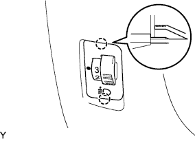
Engage the 2 claws and install the headlight leveling switch.
-
-
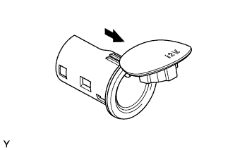
INSTALL POWER POINT SOCKET ASSEMBLY
-
Install the power outlet socket cover.
-
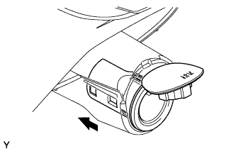
Install the power outlet socket bezel in the direction indicated by the arrow.
-
Connect the connector.
-
Align the power outlet socket with the notch on the power outlet socket bezel, and push the power outlet socket firmly into the power outlet socket cover to install it.
-
-
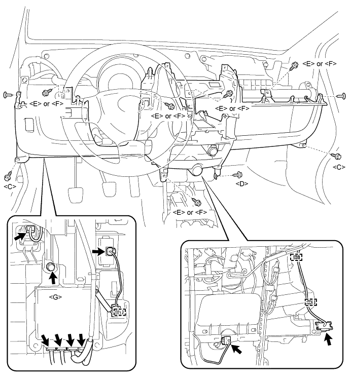
INSTALL INSTRUMENT PANEL ASSEMBLY LOWER
-
Install the instrument panel lower with the 2 bolts <C>, 5 screws <E> or <F>, screw <D>, screw <G> and 2 clips.
- Torque:
- 3.7 N*m { 38 kgf*cm, 33 in.*lbf, for screw <G> }
-
Connect the connectors and engage the 3 wire harness clamps.
-
Connect the antenna cord by engaging the 4 fastenings.
-
-
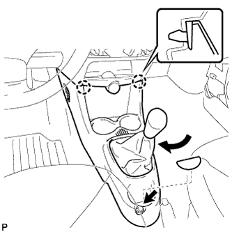
INSTALL CONSOLE BOX (for Manual Transaxle)
-
Engage the 2 claws and install the console box.
-
Install the bolt <B>.
-
Install the box bottom mat.
-
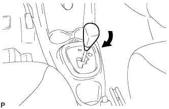
Turn the shift knob in the direction indicated by the arrow in the illustration to install it.
-
-
INSTALL CONSOLE BOX (for Multi-Mode Manual Transaxle)
-
Engage the 2 claws and install the console box.
-
Install the bolt <B>.
-
Install the box bottom mat.
-
-
INSTALL FLOOR SHIFT POSITION INDICATOR HOUSING SUB-ASSEMBLY (for Multi-Mode Manual Transaxle)
-
Engage the 4 claws and install the floor shift position indicator housing sub-assembly.
-
Turn the shift knob in the direction indicated by the arrow in the illustration to install it.
-
-
INSTALL HEATER CONTROL ASSEMBLY (for LHD)
Note
Do not bend the cable when installing the heater control assembly.
-
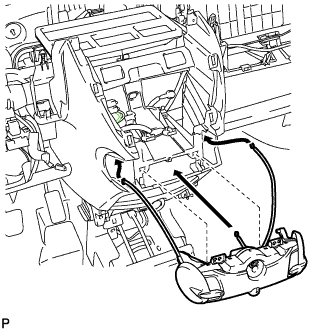
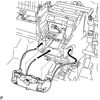
Insert each cable into the instrument panel.
-
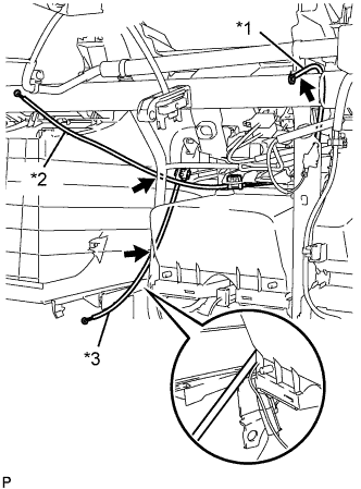
Text in Illustration *1 Defroster Cable *2 Air Inlet Cable *3 Air Mix Cable Pass the white air inlet cable between the instrument panel and wire harness.
-
Pass the black air mix cable between the instrument panel and wire harness.
-
Pass the blue defroster cable between the instrument panel reinforcement and wire harness, and then outside the wire harness clamp.
-
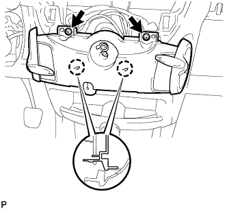
Engage the 2 claws and install the heater control assembly with the 2 screws.
-
-
INSTALL HEATER CONTROL ASSEMBLY (for RHD)
Note
Do not bend the cable when installing the heater control assembly.
-
Insert the cable into the instrument panel.
-
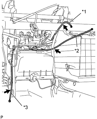
Text in Illustration *1 Defroster Cable *2 Air Inlet Cable *3 Air Mix Cable Pass the white air inlet cable through the wire harness.
-
Pass the black air mix cable between the instrument panel and brace.
-
Pass the blue defroster cable between the instrument panel reinforcement and wire harness, and then outside the wire harness clamp.
-
Engage the 2 claws and install the heater control assembly with the 2 screws.
-
-
SET HEATER CONTROL ASSEMBLY
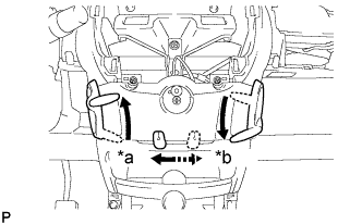
Text in Illustration *a LHD *b RHD
-
Make sure that the levers are placed in the position shown in the illustration.
-
-
CONNECT DEFROSTER DAMPER CONTROL CABLE SUB-ASSEMBLY
-
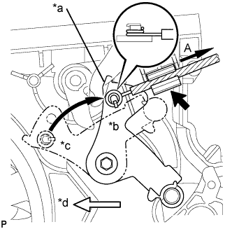
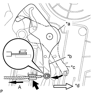
Text in Illustration *a Mode Link *b DEF *c FACE *d Front Side Turn the mode link to the DEF position.
-
Install the cable ring onto the motor link.
-
Hold the mode wheel knob of the heater control and install the defroster cable onto the clamp while pulling it in the direction indicated by arrow A.
Note
Make sure that the air mix lever knob operates correctly. Also, confirm that there is no reverse movement of the knob at either end.
-
-
CONNECT AIR MIX DAMPER CONTROL CABLE SUB-ASSEMBLY
-
Text in Illustration *a Temperature Control Link *b COOL *c WARM *d Front Side Turn the temperature control link to the MAX-cool position.
-
Install the cable ring onto the temperature control link.
-
Hold the mode wheel knob of the heater control and install the mode cable onto the clamp while pulling it in the direction indicated by arrow A.
Note
Make sure that the air mix lever knob operates correctly. Also, confirm that there is no reverse movement of the knob at either end.
-
-
CONNECT AIR INLET DAMPER CONTROL CABLE SUB-ASSEMBLY
-
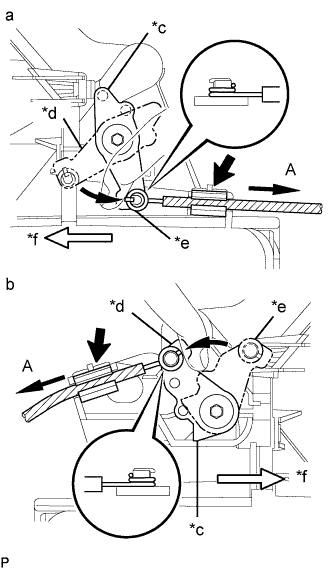
Text in Illustration *a LHD *b RHD *c Air Inlet Control Link *d FRESH *e RECIRCULATION *f Front Side Turn the air inlet control link to the RECIRCULATION position.
-
Turn the air inlet control link to the FRESH AIR position.
-
Install the cable ring onto the air inlet control link.
-
Hold the air inlet lever knob of the heater control and install the air inlet cable onto the clamp while pulling it in the direction indicated by arrow A.
Note
Make sure that the air inlet lever knob operates correctly. Also, confirm that there is no reverse movement of the knob at either end.
-
-
INSTALL COWL SIDE TRIM BOARD LH
-
Engage the 2 clips and claw, and install the cowl side trim board LH.
-
-
INSTALL COWL SIDE TRIM BOARD RH
Tech Tips
Use the same procedure as for the LH side.
-
INSTALL INSTRUMENT PANEL ASSEMBLY