WINDSHIELD GLASS INSTALLATION

-
CLEAN WINDSHIELD GLASS
-
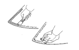
Using a scraper, remove the damaged stoppers, dam and adhesive sticking to the windshield glass.
-
Clean the outer circumference of the windshield glass with white gasoline.
Note
-
Do not touch the windshield glass surface after cleaning it.
-
Even if using a new windshield glass, clean the windshield glass with white gasoline.
-
-
-
CLEAN VEHICLE BODY
-
Clean and shape the contact surface of the vehicle body.
-
Using a knife, cut away any rough adhesive on the contact surface of the vehicle body to ensure the appropriate surface shape.
Note
Do not damage the vehicle body.
Tech Tips
Leave as much adhesive on the vehicle body as possible.
-
Clean the contact surface of the vehicle body with a shop rag or piece of cloth saturated with cleaner.
Tech Tips
Clean the vehicle body even if all the adhesive has been removed.
-
-
-
INSTALL WINDSHIELD GLASS STOPPER NO.2
-
Apply Primer G to the installation part of the stoppers.
Note
-
Allow the primer to dry for 3 minutes or more.
-
Throw away any leftover Primer G.
-
Do not apply too much Primer G.
-
-
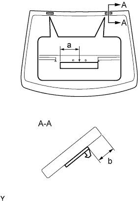
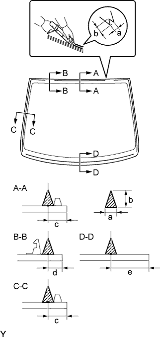
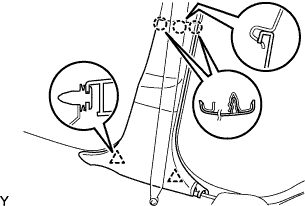
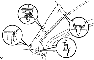
Install 2 new stoppers onto the windshield glass, as shown in the illustration.
Specification Area Measurement a 40 mm ( in.) b 14 mm (0.55 in.)
-
-
INSTALL WINDSHIELD GLASS STOPPER NO.1
-
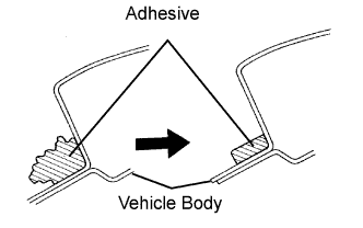
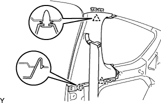
Install 2 new stoppers onto the vehicle body, as shown in the illustration.
-
-
INSTALL WINDSHIELD GLASS ADHESIVE DAM
-
Apply Primer G to the part of the dam shown in the illustration.
Note
-
Allow the primer to dry for 3 minutes or more.
-
Throw away any leftover Primer G.
-
Do not apply too much Primer G.
-
-
Install 3 new dams. Install the 3 dams by applying double-sided tape all the way around the windshield glass except where the stoppers are installed, as shown in the illustration.
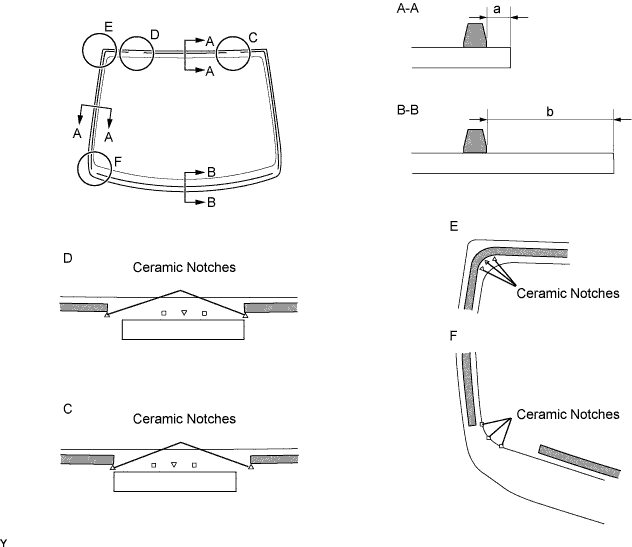
Specification Area Measurement a 4 mm (0.55 in.) b 31.5 mm (1.240 in.)
-
-
INSTALL WINDSHIELD GLASS
-
Position the windshield glass.
-
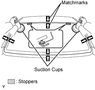
Using suction cups, place the windshield glass in the correct position.
-
Check that the entire contact surface of the windshield glass rim is perfectly even.
-
Place matchmarks over the windshield glass and vehicle body.
Note
Check that the stoppers are correctly attached to the vehicle body.
Tech Tips
When reusing a windshield glass, check and correct the matchmark positions.
-
Using suction cups, remove the windshield glass.
-
-
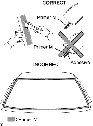
Using a brush, apply Primer M to the exposed part of the vehicle body.
Note
-
Allow the primer to dry for 3 minutes or more.
-
Do not apply Primer M to the adhesive.
-
Throw away any leftover Primer M.
-
Do not apply too much Primer M.
-
-
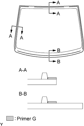
Using a brush or sponge, apply Primer G to the edge of the windshield glass and the contact surface.
Note
-
Allow the primer to dry for 3 minutes or more.
-
Throw away any leftover Primer G.
-
Do not apply too much Primer G.
Tech Tips
If Primer G is applied to any areas other than those specified, wipe off the primer with a clean shop rag or a piece of cloth before it dries.
-
-
Apply adhesive.
Adhesive Part No. 08850-00801 or equivalent
-
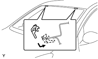
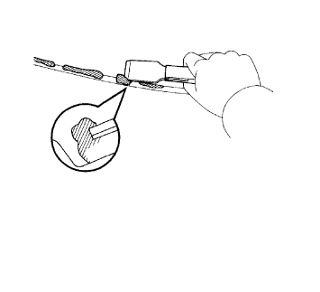
Cut the tip off the cartridge nozzle, as shown in the illustration.
Tech Tips
After cutting off the tip, use all adhesive within the times indicated in the table bellow.
Usage Time Frame Temperature Usage Time Frame 35°C (95°F) 15 minutes 20°C (68°F) 1 hour 40 minutes 5°C (41°F) 8 hours -
Load the sealer gun with the cartridge.
-
Apply adhesive to the windshield glass, as shown in the illustration.
Specification Area Measurement a 8 mm (0.315 in.) b 12 mm (0.472 in.) c 13 mm (0.512 in.) d 10.3 mm (0.406 in.) e 27.5 mm (1.083 in.)
-
-
Install the windshield glass onto the vehicle body.
-
Using suction cups, position the windshield glass so that the matchmarks are aligned. Gently press it in along the rim.
Note
-
Allow the primer to dry for 3 minutes or more.
-
Check that the stoppers are attached to the vehicle body correctly.
-
Check that there is a small gap between the vehicle body and windshield glass.
-
-
Gently press the front surface of the windshield glass to ensure that the windshield glass is securely fitted to the vehicle body.
-
Using a scraper, remove any excessive or protruding adhesive.
Tech Tips
Apply adhesive to the windshield glass rim.
-
-
-
CHECK FOR LEAKAGE AND REPAIR
-
Conduct a leak test after the adhesive has completely hardened.
-
Seal any leaks with auto glass sealer.
-
-
INSTALL COWL TOP VENTILATOR LOUVER RH
-
Connect the washer hose.
-

Engage the 8 claws and install the cowl top ventilator louver RH.
-
Install the clip.
-
-
INSTALL COWL TOP VENTILATOR LOUVER LH
-
Connect the washer hose.
-
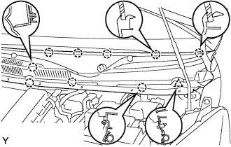
Engage the 9 claws and install the cowl top ventilator louver LH.
-
Install the clip.
-
-
INSTALL HOOD TO COWL TOP SEAL

-
Engage the 8 clips and install the hood to cowl top seal.
-
-
INSTALL FRONT WIPER ARM
-
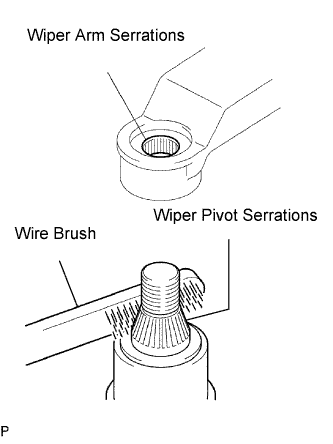
Scrape any metal powder off the serrated part of the wiper arm with a round file or equivalent (when reinstalling).
-
Clean the wiper pivot serrations with a wire brush.
-
Operate the wiper, then stop the windshield wiper motor assembly in the automatic stop position.
-
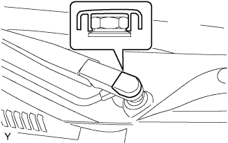
Provisionally install the front wiper main arm with the nut.
-
Install the front wiper secondary arm onto the front wiper motor and link assembly.
-
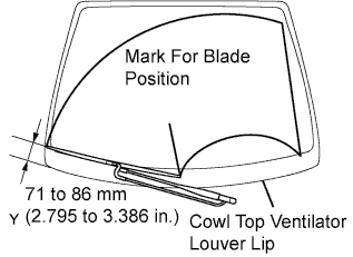
Align the blade tip with the mark on the windshield glass, as shown in the illustration.
-
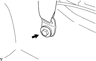
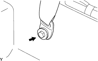
Tighten the nut of the front wiper main arm.
- Torque:
- 21 N*m { 209 kgf*cm, 15 ft.*lbf }
-
-
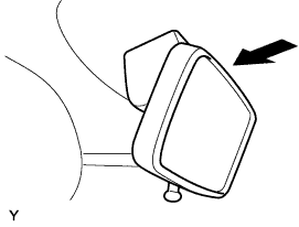
INSTALL FRONT WIPER ARM HEAD CAP
-
Engage the claw and install the front wiper arm head cap.
-
-
INSTALL INNER REAR VIEW MIRROR ASSEMBLY
-
Install the inner rear view mirror assembly, as shown in the illustration.
-
-
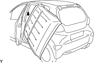
INSTALL ROOF HEADLINING ASSEMBLY (for 5 Door)
-
Gently remove the backing sheet and any adhesive remaining on the roof panel.
Tech Tips
It is not necessary to remove the adhesive completely.
-
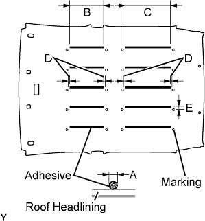
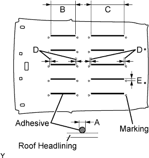
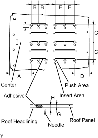
Apply adhesive (Henkel Terostat 8595N/MT) to a new roof headlining.
Specification Area Measurement A φ6 to 8 mm (0.236 to 0.315 in.) B 290 mm (11.417 in.) C 395 mm (15.551 in.) D 20 to 30 mm (0.787 to 1.181 in.) Note
-
Apply adhesive 20 to 30 mm (0.787 to 1.181 in.) away from the markings placed on the roof headlining.
-
Avoid adhesive accumulation.
-
-
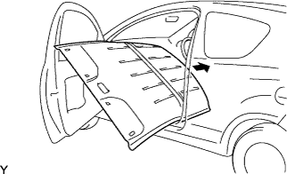
Install the roof headlining onto the vehicle.
-
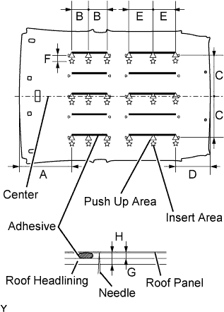
Push the roof headlining up to the roof panel until the distance between the roof panel and the backing sheet is less than 4 mm (0.157 in.) at all 18 points shown in the illustration.
Specification Area Measurement A 430 mm (16.929 in.) B 145 mm (5.709 in.) C 335 mm (13.189 in.) D 280 mm (11.024 in.) E 197 mm (7.756 in.) F 20 mm (0.787 in.) G 4 mm or less (0.157 in. or less) H 10 mm or less (0.394 in. or less) Note
-
Be sure to press the roof headlining onto the roof panel with clean hands.
-
Gently and uniformly press the whole roof headlining since pressing it locally could damage it.
-
-
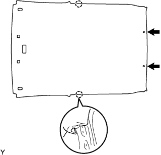
Insert a clean needle into the 18 points shown in the illustration from the roof headlining side, and press the roof headlining until the distance between the roof panel and roof headlining surface is less than 10 mm (0.394 in.).
Note
Do not stick the needle into areas where adhesive is applied, as this could make the roof headlining dirty.
-
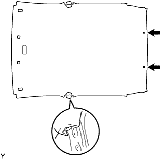
Engage the 2 hooks
-
Install the 2 clips.
-
-
INSTALL ROOF HEADLINING ASSEMBLY (for 3 Door)
-
Gently remove the backing sheet and any adhesive remaining on the roof panel.
Tech Tips
It is not necessary to remove the adhesive completely.
-
Apply adhesive (Henkel Terostat 8595N/MT) to a new roof headlining.
Specification Area Measurement A φ6 to 8 mm (0.236 to 0.315 in.) B 290 mm (11.417 in.) C 395 mm (15.551 in.) D -10 to 10 mm (-0.394 to 0.394 in.) E 20 to 30 mm (0.787 to 1.181 in.) Note
-
Apply adhesive 20 to 30 mm (0.787 to 1.181 in.) away from the markings placed on the roof headlining.
-
Avoid adhesive accumulation.
-
-
Install the roof headlining onto the vehicle.
-
Push the roof headlining up to the roof panel until the distance between the roof panel and the backing sheet is less than 4 mm (0.157 in.) at all 18 points shown in the illustration.
Specification Area Measurement A 430 mm (16.929 in.) B 145 mm (5.709 in.) C 335 mm (13.189 in.) D 280 mm (11.024 in.) E 197 mm (7.756 in.) F 20 mm (0.787 in.) G 4 mm or less (0.157 in. or less) H 10 mm or less (0.394 in. or less) Note
-
Be sure to press the roof headlining onto the roof panel with clean hands.
-
Gently and uniformly press the whole roof headlining since pressing it locally could damage it.
-
-
Insert a clean needle into the 18 points shown in the illustration from the roof headlining side, and press the roof headlining until the distance between the roof panel and roof headlining surface is less than 10 mm (0.394 in.).
Note
Do not stick the needle into areas where adhesive is applied, as this could make the roof headlining dirty.
-
Engage the 2 hooks.
-
Install the 2 clips.
-
-
INSTALL ROOM LIGHT ASSEMBLY
-
Install the bulb.
-
Install the connector cover.
-
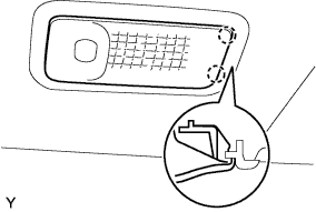
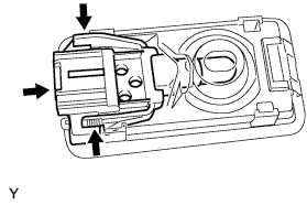
Engage the 2 claws and install room light assembly No. 1.
-
Connect the connector and engage the 4 claws.
-
-
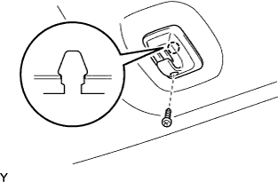
INSTALL VISOR HOLDER
Tech Tips
Use the same procedure as for the opposite side.
-
Engage the claw and install the visor holder.
-
Tighten the screw.
-
-
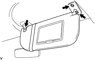
INSTALL VISOR ASSEMBLY RH
-
Install the visor with the 2 screws.
-
Install the visor into the visor holder.
-
-
INSTALL VISOR ASSEMBLY LH
Tech Tips
Use the same procedure as for the RH side.
-
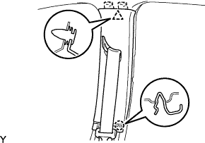
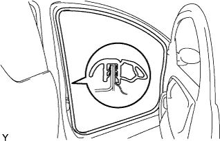
INSTALL CENTER PILLAR GARNISH UPPER RH (for 5 Door)
-
Pass the front seat outer belt through the slit of the center pillar garnish.
-
Engage the clip and claw, and install the center pillar garnish.
-
-
INSTALL CENTER PILLAR GARNISH UPPER RH (for 3 Door)
-
Pass the front seat outer belt through the slit of the center pillar garnish.
-
Engage the claw and 2 clips, and install the center pillar garnish.
-
-
INSTALL CENTER PILLAR GARNISH UPPER LH (for 5 Door)
Tech Tips
Use the same procedure as for the RH side.
-
INSTALL CENTER PILLAR GARNISH UPPER LH (for 3 Door)
Tech Tips
Use the same procedure as for the RH side.
-
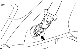
INSTALL FRONT SEAT OUTER BELT ASSEMBLY RH (for 5 Door)
-
Install the lap outer anchor plate of the front seat outer belt with the bolt.
- Torque:
- 42 N*m { 430 kgf*cm, 31 ft.*lbf }
-
-
INSTALL FRONT SEAT OUTER BELT ASSEMBLY RH (for 3 Door)
-
Install the lap outer anchor plate of the front seat outer belt with the bolt.
- Torque:
- 42 N*m { 430 kgf*cm, 31 ft.*lbf }
-
-
INSTALL FRONT SEAT OUTER BELT ASSEMBLY LH (for 5 Door)
Tech Tips
Use the same procedure as for the RH side.
-
INSTALL FRONT SEAT OUTER BELT ASSEMBLY LH (for 3 Door)
Tech Tips
Use the same procedure as for the RH side.
-
INSTALL CENTER PILLAR GARNISH LOWER RH (for 5 Door)
-
Engage the 2 clips and 3 claws, and install the center pillar garnish.
-
-
INSTALL CENTER PILLAR GARNISH LOWER LH (for 5 Door)
Tech Tips
Use the same procedure as for the RH side.
-
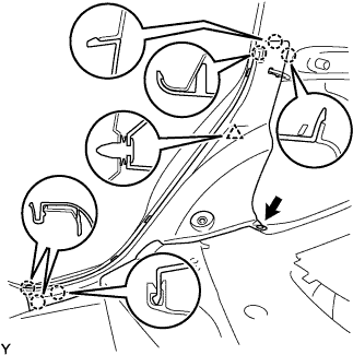
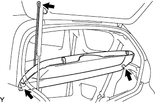
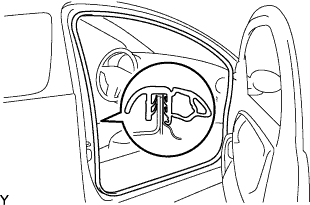
INSTALL ROOF SIDE GARNISH INNER RH (for 5 Door)
-
Pass the rear seat outer belt through the slit of the roof side garnish.
-
Engage the 3 clips and claw, and install the roof side inner garnish.
-
Tighten the screw.
-
Install the clip.
-
-
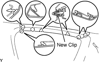
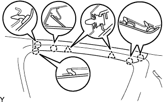
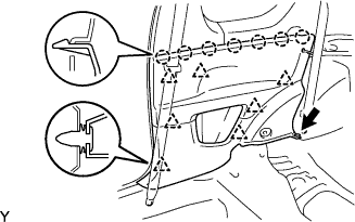
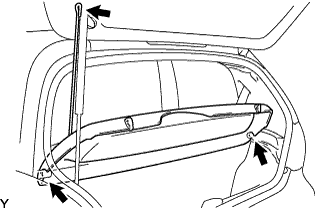
INSTALL ROOF SIDE GARNISH INNER RH (for 3 Door)
-
Pass the rear seat outer belt through the slit of the roof side garnish.
-
Engage the 4 claws and 7 clips, and install the roof side garnish.
-
Tighten the screw.
-
Install the clip.
-
-
INSTALL ROOF SIDE GARNISH INNER LH (for 5 Door)
Tech Tips
Use the same procedure as for the RH side.
-
INSTALL ROOF SIDE GARNISH INNER LH (for 3 Door)
Tech Tips
Use the same procedure as for the RH side.
-
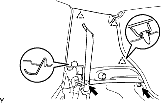
INSTALL ROOF SIDE RAIL GARNISH REAR RH (for 3 Door, w/ Curtain Shield Airbag)
-
Install a new clip.
-
Engage the 5 claws and 2 clips, and install the roof side rail garnish.
-
-
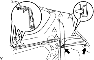
INSTALL ROOF SIDE RAIL GARNISH REAR RH (for 3 Door, w/o Curtain Shield Airbag)
-
Engage the 5 claws and 2 clips, and install the roof side rail garnish.
-
-
INSTALL ROOF SIDE RAIL GARNISH REAR LH (for 3 Door, w/ Curtain Shield Airbag)
Tech Tips
Use the same procedure as for the RH side.
-
INSTALL ROOF SIDE RAIL GARNISH REAR LH (for 3 Door, w/o Curtain Shield Airbag)
Tech Tips
Use the same procedure as for the RH side.
-
INSTALL QUARTER INSIDE TRIM BOARD RH (for 3 Door)
-
Engage the 7 claws and 7 clips, and install quarter trim board.
-
Install the clip.
-
-
INSTALL QUARTER INSIDE TRIM BOARD LH (for 3 Door)
Tech Tips
Use the same procedure as for the RH side.
-
INSTALL REAR SEAT SIDE GARNISH RH (for 5 Door)
-
Engage the clip and 6 claws, and install the rear seat side garnish.
-
Install the clip.
-
-
INSTALL REAR SEAT SIDE GARNISH LH (for 5 Door)
Tech Tips
Use the same procedure as for the RH side.
-
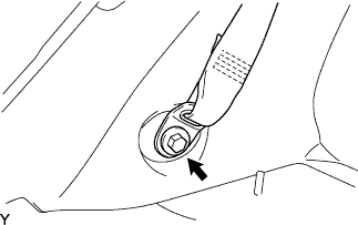
INSTALL REAR SEAT OUTER BELT ASSEMBLY RH (for 5 Door)
-
Install the lap outer anchor plate of the rear seat outer belt with the bolt.
- Torque:
- 42 N*m { 430 kgf*cm, 31 ft.*lbf }
-
-
INSTALL REAR SEAT OUTER BELT ASSEMBLY RH (for 3 Door)
-
Install the lap outer anchor plate of the rear seat outer belt with the bolt.
- Torque:
- 42 N*m { 430 kgf*cm, 31 ft.*lbf }
-
-
INSTALL REAR SEAT OUTER BELT ASSEMBLY LH (for 5 Door)
Tech Tips
Use the same procedure as for the RH side.
-
INSTALL REAR SEAT OUTER BELT ASSEMBLY LH (for 3 Door)
Tech Tips
Use the same procedure as for the RH side.
-
INSTALL PACKAGE TRAY TRIM PANEL ASSEMBLY (for 5 Door)
-
Install the package tray trim panel.
-
-
INSTALL PACKAGE TRAY TRIM PANEL ASSEMBLY (for 3 Door)
-
Install the package tray trim panel.
-
-
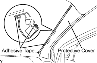
INSTALL FRONT PILLAR GARNISH RH (w/ Curtain Shield Airbag)
-
Remove the adhesive tape and protective cover.
-
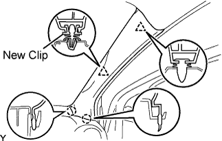
Install a new clip.
-
Engage the 2 claws and 2 clips, and install the front pillar garnish.
-
-
INSTALL FRONT PILLAR GARNISH RH (w/o Curtain Shield Airbag)
-
Engage the 2 claws and 2 clips, and install the front pillar garnish.
-
-
INSTALL FRONT PILLAR GARNISH LH (w/ Curtain Shield Airbag)
Tech Tips
Use the same procedure as for the RH side.
-
INSTALL FRONT PILLAR GARNISH LH (w/o Curtain Shield Airbag)
Tech Tips
Use the same procedure as for the RH side.
-
INSTALL FRONT DOOR OPENING TRIM WEATHERSTRIP RH (for 5 Door)
-
Install the front door opening trim weatherstrip.
-
-
INSTALL FRONT DOOR OPENING TRIM WEATHERSTRIP RH (for 3 Door)
-
Install the front door opening trim weatherstrip.
-
-
INSTALL FRONT DOOR OPENING TRIM WEATHERSTRIP LH (for 5 Door)
Tech Tips
Use the same procedure as for the RH side.
-
INSTALL FRONT DOOR OPENING TRIM WEATHERSTRIP LH (for 3 Door)
Tech Tips
Use the same procedure as for the RH side.
-
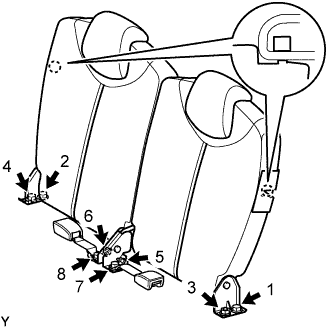
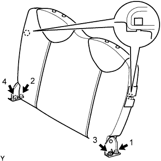
INSTALL REAR SEAT BACK ASSEMBLY (for Separate Seat Type)
-
Place the rear seat back in the cabin.
-
Using several steps, install and tighten the 4 nuts, 4 bolts and 2 rear seat inner belts uniformly in the sequence shown in the illustration.
- Torque:
- 22 N*m { 225 kgf*cm, 16 ft.*lbf, for 1, 2, 3 and 4 }
- 33.8 N*m { 345 kgf*cm, 25 ft.*lbf, for 5 and 6 }
- 42 N*m { 430 kgf*cm, 31 ft.*lbf, for 7 and 8 }
-
Lock the 2 hooks.
-
-
INSTALL REAR SEAT BACK ASSEMBLY (for Bench Seat Type)
-
Place the rear seat back in the cabin.
-
Using several steps, install and tighten the 2 nuts and 2 bolts uniformly in the sequence shown in the illustration.
- Torque:
- 22 N*m { 225 kgf*cm, 16 ft.*lbf }
-
Engage the 2 hooks.
-
-
INSTALL REAR SEAT CUSHION ASSEMBLY (for Separate Seat Type)
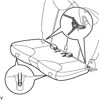
-
Engage the 4 hooks and install the rear seat cushion.
-
-
INSTALL REAR SEAT CUSHION ASSEMBLY (for Bench Seat Type)
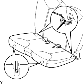
-
Engage the 4 hooks and install the rear seat cushion.
-
-
INSTALL FRONT SEAT ASSEMBLY LH
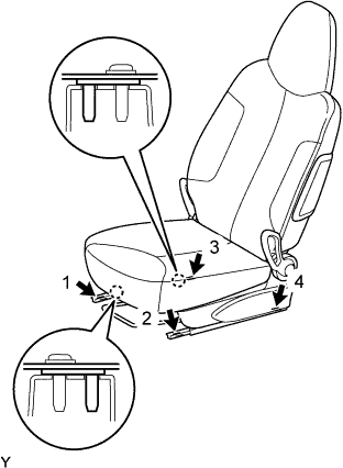
-
Place the front seat in the cabin.
-
Using several steps, install and tighten the 4 bolts uniformly in the sequence shown in the illustration.
- Torque:
- 22 N*m { 225 kgf*cm, 16 ft.*lbf }
-
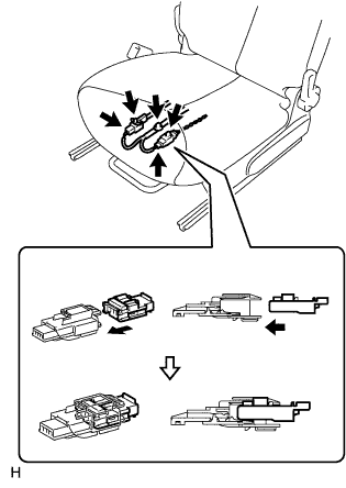
Connect the airbag connector, as shown in the illustration (w/ front seat side airbag).
-
Connect the buckle switch connector (driver seat only).
-
Install the wire harness clamp.
-
-
INSTALL FRONT SEAT ASSEMBLY RH
Tech Tips
Use the same procedure as for the LH side.
-
CONNECT CABLE TO NEGATIVE BATTERY TERMINAL
- Torque:
- 5.4 N*m { 55 kgf*cm, 48 in.*lbf }
-
INSPECT SRS WARNING LIGHT (w/ Front Seat Airbag and Curtain Shield Airbag)