AUDIO AND VISUAL SYSTEM (w/o Microphone) Speaker Circuit
DESCRIPTION
Sound signals that have been amplified by the stereo component amplifier are sent to the speakers from the radio receiver through this circuit. If there is a short in this circuit, the sound cannot be heard from the speakers even though there is no malfunction in the speakers.
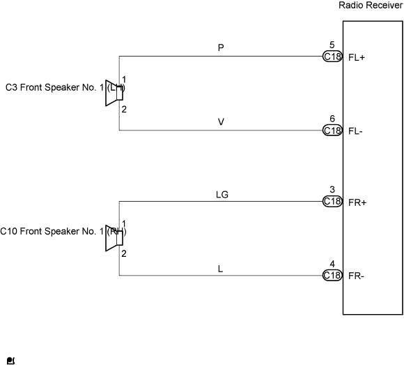
WIRING DIAGRAM
INSPECTION PROCEDURE
PROCEDURE
-
INSPECT FRONT SPEAKER NO.1
-
Measure the resistance between the terminals of the speaker.
Note
Do not remove the speakers for checking.
Standard Approximately 4 Ω -
Check that the malfunction disappears when another speaker in good condition is installed.
OK The malfunction disappears. Tech Tips
-
Connect all the connectors to the speakers.
-
When there is a possibility that either the left or right front speaker is defective, inspect by interchanging the left and right speakers.
-
NG 
REPLACE FRONT SPEAKER NO.1
OK 
-
-
CHECK HARNESS AND CONNECTOR
-
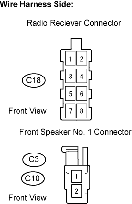
Disconnect the C18 radio receiver connector.
-
Disconnect the C3 and C10 speaker connectors.
-
Check the resistance.
Standard Resistance Tester Connection Specified Condition FL+ (C18-5) - C3-1 Below 1 Ω FL- (C18-6) - C3-2 Below 1 Ω FR+ (C18-3) - C10-1 Below 1 Ω FR- (C18-4) - C10-2 Below 1 Ω FL+ (C18-5) or C3-1 - Body ground 10 kΩ or higher FL- (C18-6) or C3-2 - Body ground 10 kΩ or higher FR+ (C18-3) or C10-1 - Body ground 10 kΩ or higher FR- (C18-4) or C10-2 - Body ground 10 kΩ or higher -
Reconnect the radio receiver connector.
-
Reconnect the speaker connectors.
NG
REPAIR OR REPLACE HARNESS OR CONNECTOR
OK 
PROCEED TO NEXT CIRCUIT INSPECTION SHOWN IN PROBLEM SYMPTOMS TABLE
-